Foot-operated toilet seat

a toilet seat and foot-operated technology, which is applied in the field of foot-operated mechanism for raising the toilet seat, can solve the problems of unfettered access to the toilet bowl, and achieve the effects of convenient installation, low cost, and simple structur

Inactive Publication Date: 2006-11-14
STEWART STEVE
View PDF9 Cites 7 Cited by
  • Summary
  • Abstract
  • Description
  • Claims
  • Application Information

AI Technical Summary

Benefits of technology

[0005]The present disclosure provides a simple, easy to manufacture, and cost effective solution to the age-old problem of lifting the toilet seat in order to use the toilet as a urinal in a sanitary and convenient manner. The present disclosure will overcome this problem by utilizing a very simple foot-operated mechanism to lift the seat while using the toilet as a urinal. It can be inexpensively mass produced and can be easily fitted to new and existing popular toilet models.
[0006]Instead of fumbling for a finger-hold around the bottom of the toilet seat, a foot-operated device is more convenient and keeps a user's hands away from the toilet bowl. Using a robust two geared shaft design and a single lever, this invention can be installed quickly on new toilets, and can easily replace or supplement conventional toilet seats on popular existing toilet models.
[0007]The present disclosure is operated by means of a mechanical assembly near the rear base of the toilet seat, mounted near the rear edge of the toilet bowl, in front of the toilet tank, and consisting of a pair of geared shafts, one attached to the toilet seat and the other attached to an adjustable lever that extends down one side of the toilet bowl, at an angle, toward the floor, terminating in a foot pedal a few inches above the floor itself Downward pressure on the foot pedal causes the rear shaft to rotate toward the front of the toilet bowl, with the gearing then forcing the front shaft to rotate in the opposite direction. This front shaft is connected to the toilet seat at its rear base, causing it to lift up from the toilet bowl as the shaft is rotated. Its maximum travel is almost 90 degrees from the closed position, resulting in unfettered access to the toilet bowl. Releasing pressure on the pedal reverses the process, with gravity causing the seat to lower back into the horizo...

Problems solved by technology

Its maximum travel is almost 90 degrees from the closed...

Method used


Image

  • Foot-operated toilet seat
  • Foot-operated toilet seat
  • Foot-operated toilet seat

Examples


Embodiment Construction

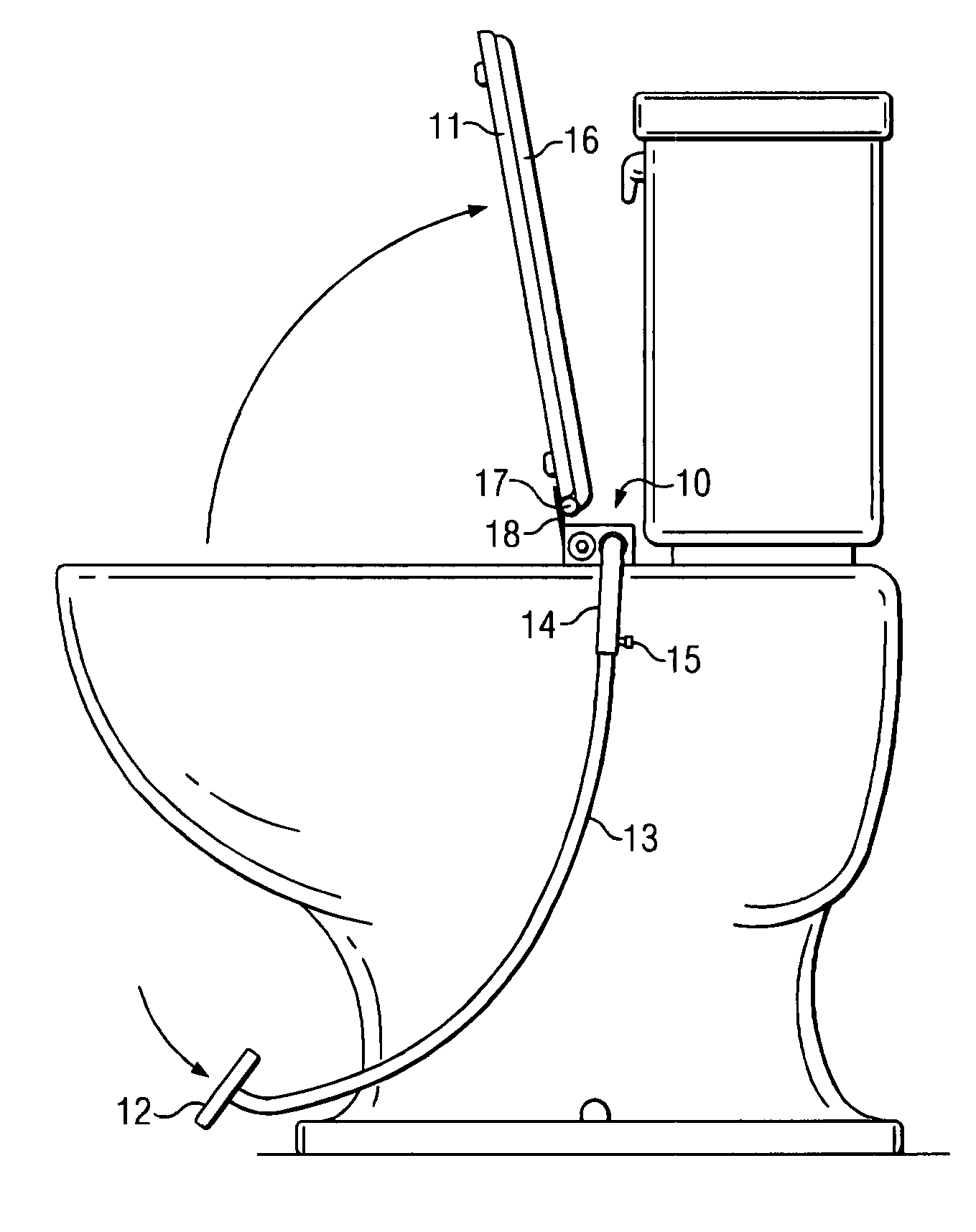
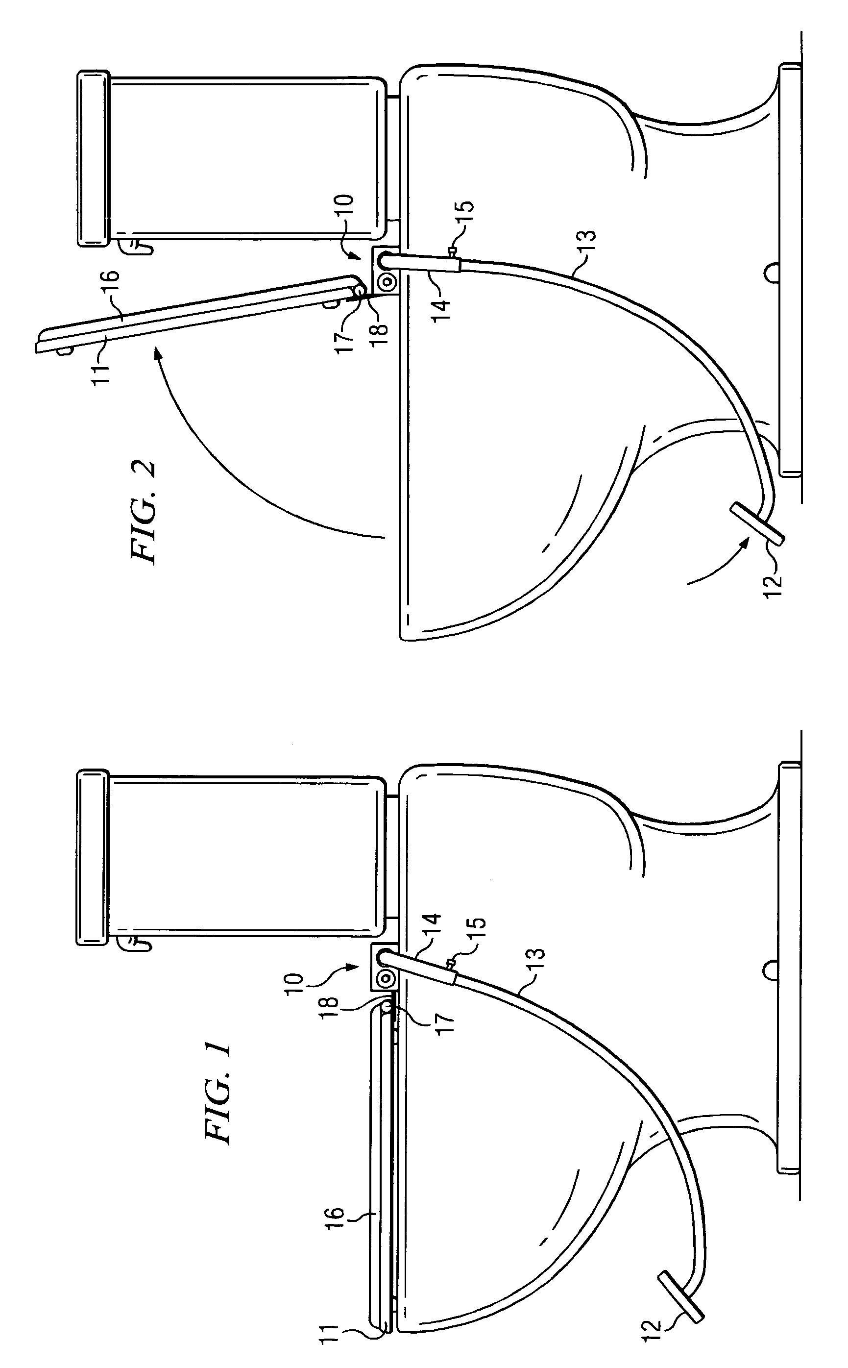
[0016]Referring to FIG. 1, a foot-operated mechanism 10 is shown in a side perspective, mounted on a typical toilet, just in front of the tank, on the rear edge of the toilet bowl. In a lowered position, the toilet seat 11 rests on the edge of the toilet bowl, with the foot pedal 12 in a normal position above the floor. The lower lever 13 to which the foot pedal 12 is attached is slightly smaller in diameter than an upper lever 14, allowing for an adjusting friction screw 15 to be used to adjust the extension length of the lower lever 13, and thus the distance from the foot pedal 12 distance above the floor. A toilet seat cover 16 is mounted on a hinge 17 just to the rear of the toilet seat and on top of a metal flange 18.

[0017]FIG. 2 depicts the foot-operated mechanism 10 shown in a side perspective with the toilet seat 11 in a raised position. Note that as the foot pedal 12 is depressed, the toilet seat 11 and toilet seat cover 16 are lifted into the raised position.
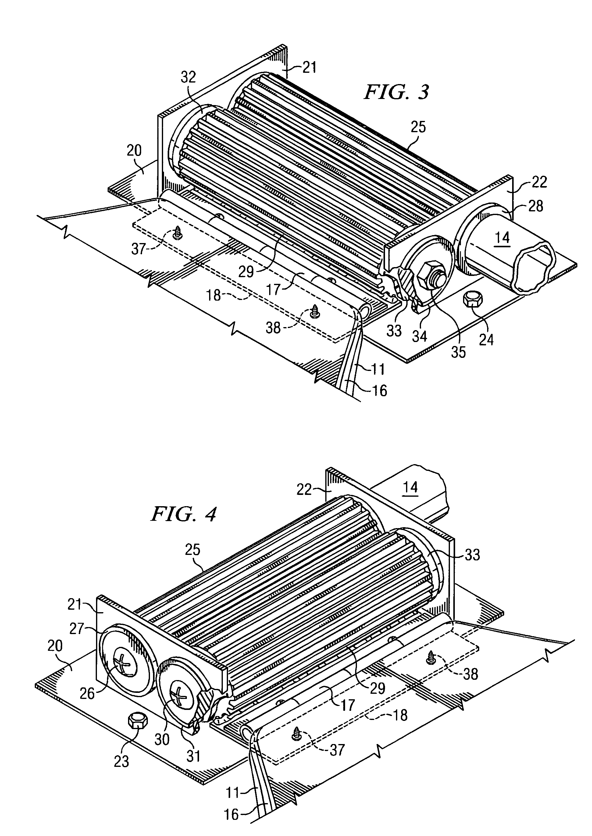
[0018]FIG. 3 d...


PUM


Abstract

A mechanism for raising a toilet seat includes two geared shafts that are cooperatively engaged while mounted on a toilet. A foot-operated lever attached to a first of the geared shafts provides torque thereto, causing a rotation of the first geared shaft upon depressing the lever. This, in turn, causes a rotation of the second of the geared shafts. The second geared shaft includes a metal flange or other connector that secures a toilet seat thereto over the bowl of the toilet. As the two geared shafts rotate, the toilet seat raises and lowers with the movement of the metal flange on the second geared shaft.

Description

CROSS-REFERENCE TO RELATED APPLICATIONS[0001]The present application claims priority under 35 U.S.C. §119(e) to U.S. Provisional Patent Application Ser. No. 60 / 428,672 entitled FOOT OPERATED TOILET SEAT filed in the name of Steve Stewart on Nov. 25, 2002, the entirety of which is incorporated herein by reference.FIELD OF THE INVENTION[0002]The present disclosure relates to a toilet seat adjusting mechanism for residential or commercial toilets, and more specifically relates to a foot-operated mechanism for raising a toilet seat that results in improved sanitation and convenience to all users of the toilet.BACKGROUND OF THE INVENTION[0003]Most toilets in the developed western world have a seat. The typical seat is a moveable device, to be manually lifted when using the toilet as a urinal. Seat design, however, has never favored this fact, and it is very common to this day to fumble for a finger-hold on the bottom edge of toilet seats in both public and residential bathrooms in order ...

Claims


Application Information

Patent Timeline
IPC IPC(8): A47K13/10
CPCA47K13/10
Inventor STEWART, STEVE
Owner STEWART STEVE
Why Eureka
Try Eureka