Stop valve for a portable pressurized-gas container, in particular for a compressed-air bottle for diving applications

a technology of stop valve and pressurized gas, which is applied in the direction of gas/liquid distribution and storage, underwater equipment, vessel construction details, etc., can solve the problems of high manufacturing cost, large stock management of different designs, and high logistics costs, and achieve the effect of easy production

Inactive Publication Date: 2006-11-14
JOHNSON OUTDOORS VERTRIEBSMBH
View PDF10 Cites 1 Cited by
  • Summary
  • Abstract
  • Description
  • Claims
  • Application Information

AI Technical Summary

Benefits of technology

[0006]It is an object of the present invention to provide a simple and economical design of a stop valve that is easily adaptable to different situations, in particular to different connection threads. Furthermore tightness problems at the valve seat should be easily and economically repairable.
[0011]Main bolts can advantageously be made with different gas container connection threads and be kept in stock. Also, valve body parts with different outlet connection threads and as required different spindle drive receiving threads can be produced and stocked. Depending on circumstances and desired individual cases, different combinations of valve body parts and main bolts can easily be combined with each other, so that different stop valve variants can be installed with a reduced number of different parts. This advantageously results in reduced manufacturing costs and reduced storage maintenance costs.
[0012]Another advantage is the fact that the valve seat parts can also be installed as individual parts and are attached by the inserted main bolt. Thereby the valve seat element can be exchanged advantageously in case of wear on a valve seat without the expensive necessity of having to replace the entire valve body as was required until now. In case of different requirements concerning sealing and through-flow of gas, a stop valve can in addition be adapted easily to these requirements by means of a differently sized valve seat without having to provide an entirely new valve body version.
[0021]As an additional feature, every outlet gas line going from a valve seat gas chamber to the bottom area of an associated outlet connection adapter is in the form of a straight, direct outlet gas line in the valve body element. This is an embodiment that can easily be produced.
[0023]In a further feature, the spindle drive consists of a screw-in part that can be screwed into the spindle drive receiving adapter with a rotatable upper spindle extending out of the screw-in part and with an adjustable lower spindle with seating seal that is coupled to it and adjustable relative to the valve seat. This is a functionally reliable, easily produced and easily installed embodiment of a spindle drive.

Problems solved by technology

This requires on the one hand high manufacturing expenditures and on the other hand extensive stock management of different designs together with costly logistics.
In addition the manufacturing technology for the production and machining of the valve seats in the bottom area of the spindle drive receiving adapters is expensive.

Method used


Image

  • Stop valve for a portable pressurized-gas container, in particular for a compressed-air bottle for diving applications
  • Stop valve for a portable pressurized-gas container, in particular for a compressed-air bottle for diving applications
  • Stop valve for a portable pressurized-gas container, in particular for a compressed-air bottle for diving applications

Examples


first embodiment

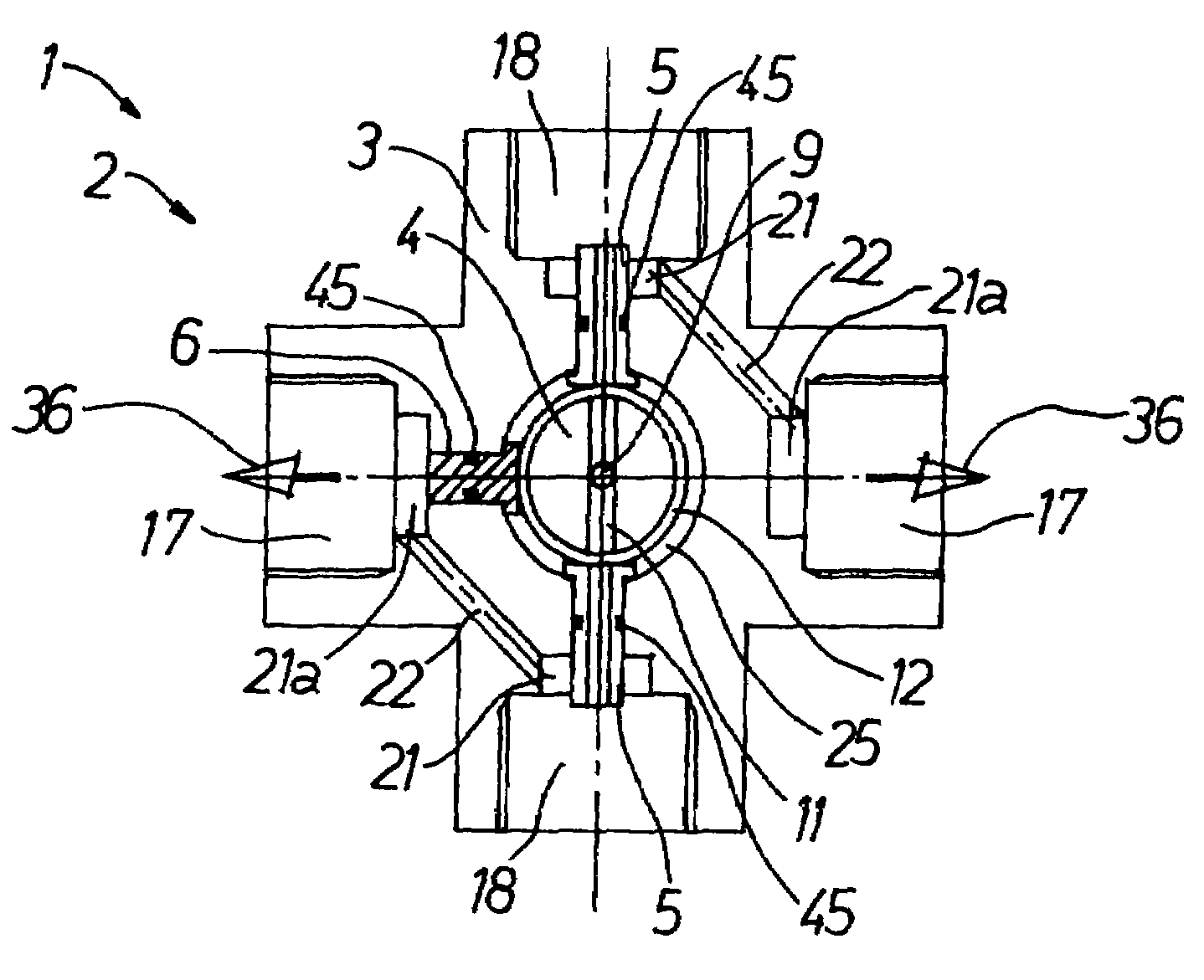
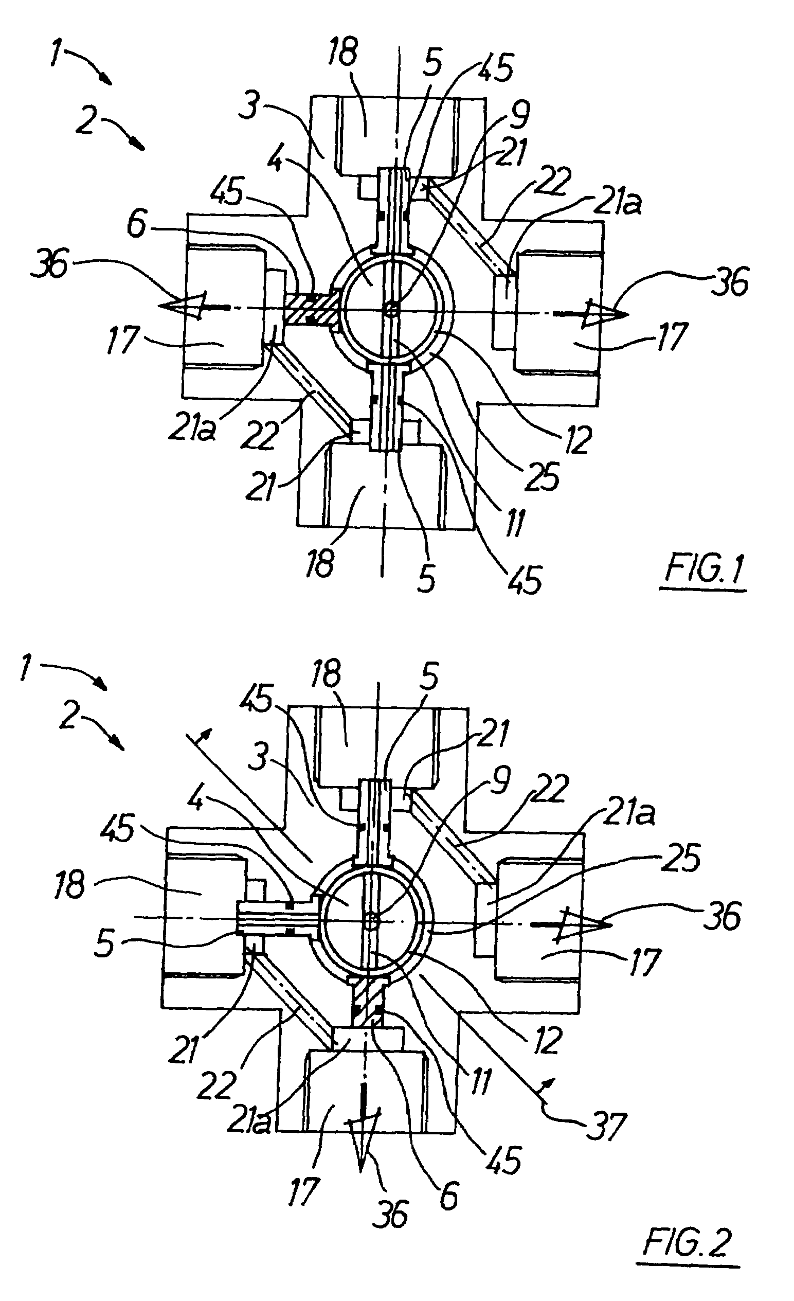
[0039]The invention will now be described in detail. Looking first at FIG. 1, a schematic sectional view through a stop valve 1 in a first embodiment is shown. The stop valve 1 has a valve body 2 made in several parts. The valve body 2 consists of a valve body element 3, a main bolt 4, two oblong valve seat elements 5 and a blind plug 6. These components of the valve body 2 are shown as individual parts in FIGS. 5 to 12, and these are described below in order to promote better overall understanding.

[0040]FIG. 5 shows a schematic longitudinal section through the main bolt 4, that is provided with tank connection threads 8. An axially oriented central gas supply bore 9 is formed in the main bolt 4. The tank connection threads 8 are in the form of outside threads, whereby a radially oriented safety bore 10 forming a connection between the central gas supply bore 9 and the outside of the main bore 4 is provided at the end of the tank connection threads 8. The central gas supply bore 9 e...

second embodiment

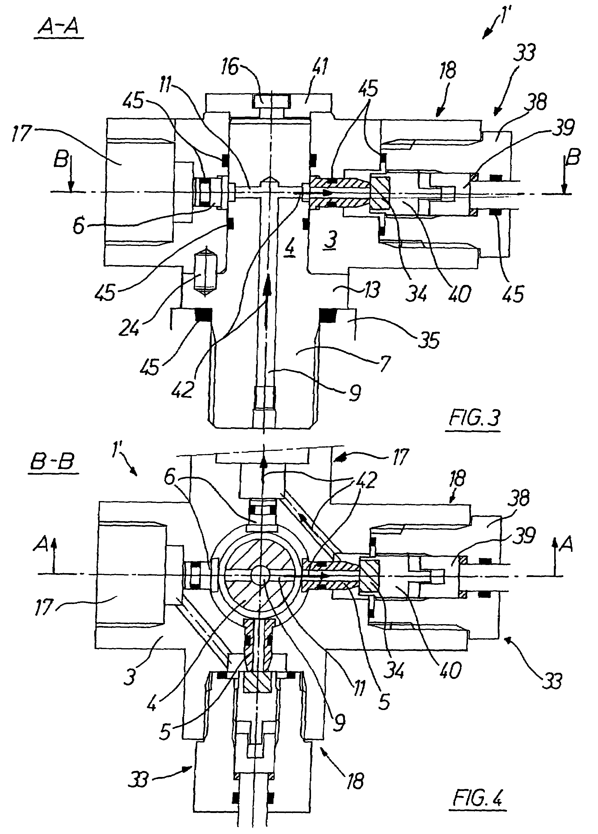
[0053]FIG. 3 shows a schematic sectional view along the sectional plane A—A of FIG. 4 of a stop valve 1′ in a Components with the same functions as in the stop valve 1 are given the same reference numbers. As is shown in FIG. 4 in a schematic sectional view along the sectional plane B—B of FIG. 3, each connection adapter is assigned a valve seat element receiving bore 20 in the embodiment of stop valve 1′. The embodiment shown in FIG. 4 is a corner valve arrangement, whereby a spindle drive 33 is screwed into the spindle drive receiving adapter 18. The spindle drive receiving adapters 18 are assigned valve seat elements 5 and the outlet connection adapters 17 are assigned blind plugs 6 in the corresponding valve seat element receiving bores 20.

[0054]he spindle drive 33 consists of a screw-in element 38 that can be screwed into the spindle drive receiving adapter 18 from which a rotatable upper spindle 39 protrudes. A lower spindle 40 adjustable relative to the valve seat 30 is coup...

third embodiment

[0057]In the embodiments of the stop valves 1 and 1′ described so far the outlet gas line 22 going from the valve seat gas chamber 21 to the bottom area 21a of the outlet connection adapter 17 is in the form of a straight and direct gas outlet bore in the valve body element 3. In a stop valve 1″ shown in FIGS. 13 and 14 the outlet gas line 22a comes from the valve seat gas chamber 21 and goes through a gas outlet groove 43 surrounding the main bolt 4. From there the outlet gas line 22a continues on the circumference of the main bolt 4 and offset relative to the bottom area 21a of the associated outlet connection adapter 17. The stop valve 1″ is shown in FIG. 13 in a schematic sectional view in axial direction of the main bolt 4, whereby FIG. 14 shows a sectional view through the stop valve 1″ that is rotated by 90° around the longitudinal axis of the main bolt 4 from the position shown in FIG. 13. As can be seen from the arrangement of the valve seat elements 5 and of the blind plug...


PUM


Abstract

The invention relates to a stop valve (1, 1′, 1″) for a portable pressurized-gas container (35). A valve body (2) is provided with three connection adapters (7, 17, 18), i.e. one central connection adapter as a gas tank connection adapter (7), another connection adapter as outlet connection adapter (17) and a third connection adapter as spindle drive receiving adapter (18). Valve body (2) is made in several parts including valve body element (3) with the outlet connection adapter (17) and a spindle drive receiving adapter (18) and a radial valve seat element receiving bore (20) going to the bottom of the spindle drive receiving adapter (18). Furthermore, the valve body (2) has an oblong valve seat element (5) with gas supply bore (29) provided at the one end of the valve seat (30) and a bearing collar (26) on the other end. In its assembled state, the valve seat element (5) is inserted tightly into the radial bolt receiving bore (20). In addition, the valve body (2) has a main bolt (4) which is inserted tightly into the central main bolt receiving bore (19). Suitable gas supply bores (9, 11, 29) allow gas to flow from the connected pressurized-gas container (35) via the spindle drive receiving adapter (13) to the outlet connection adapter (17).

Description

CROSS REFERENCE TO RELATED APPLICATION[0001]This application claims priority from German Patent Application No. 103 42 103.3 filed Sep. 10, 2003.FIELD OF THE INVENTION[0002]The invention relates to a stop valve for a portable pressurized-gas container, in particular for a compressed-air bottle for diving applications.BACKGROUND[0003]A generally known stop valve for a compressed-air bottle for diving applications is, in one design, in the form of a single connection valve consisting of one valve body with three connection adapters. The central connection adapter is a connection adapter for a gas container and, as such, it is provided with threads for the connection of the gas container, being as a rule an outside thread. The two additional connection adapters which are offset in axial direction are made in the form of outlet and connection adapters and as spindle drive receiving adapters and are axially offset, lying in a transversal plane radial to the axis of the gas container conn...

Claims


Application Information

Patent Timeline
Patent Type & Authority Patents(United States)
IPC IPC(8): F17D1/00B63C11/22F16K11/085F17C13/04
CPCB63C11/22F16K11/085F17C13/04F17C2201/058F17C2205/0323F17C2205/0385F17C2221/031F17C2223/0123F17C2223/036F17C2270/0781Y10T137/5196Y10T137/5109
Inventor HUBER, ROBERT L.STOSS, ROBERT
Owner JOHNSON OUTDOORS VERTRIEBSMBH
Why Eureka
Try Eureka