Positioning pins for multiwell test apparatus

a multi-well, test apparatus technology, applied in the direction of instruments, separation processes, laboratory glassware, etc., can solve the problems of contamination, spillover into adjacent wells, inacceptable contamination, etc., and achieve the effect of easy separation from each other

Inactive Publication Date: 2006-11-14
MILLIPORE CORP
View PDF12 Cites 11 Cited by
  • Summary
  • Abstract
  • Description
  • Claims
  • Application Information

AI Technical Summary

Benefits of technology

[0010]The present invention provides a multiwell filter plate comprising a multiplicity of wells each including a membrane for retaining a sample, such as cells on the membrane for use in a multiwell test apparatus. The multiwell filter plate is provided with at least two posts which mate with holes of a complementary receiver plate. The posts and mating holes are shaped to permit the multiwell filter plate and the receiver plate to be separated from each other easily and to permit controlled lateral transport of the multiwell filter plate relative to the receiver plate. This lateral transport permits contact of the outside well walls of the multiwell filter plate with the inside well walls of the receiver plate. This contact provides a means for removing excess liquid from the membranes of the multiwell filter plate by surface tension and capillary action.
[0011]The posts and mating holes also are shaped and positioned so that the wells of the multiwell filter plate are spaced from and do not contact the wells of the multiwell embodiment of the receiver plate while the two plates are positioned together. This well separation prevents liquid in the wells from being transported to an adjacent well by capillary action.

Problems solved by technology

These forces result in liquid in the multiwell receiver plate moving up the wall of the well to the top of the multiwell receiver plate resulting in spill-over into an adjacent well and contamination.
This contamination is unacceptable.

Method used


Image

  • Positioning pins for multiwell test apparatus
  • Positioning pins for multiwell test apparatus
  • Positioning pins for multiwell test apparatus

Examples


Embodiment Construction

[0017]While the present invention is described with reference to effecting cell growth in a multiplicity of wells, it is to be understood that the present invention is applicable to manipulations involving access areas for introducing or removing a liquid to effect the desired processing, for example dialysis or diffusional separation while avoiding movement of membranes in the wells.

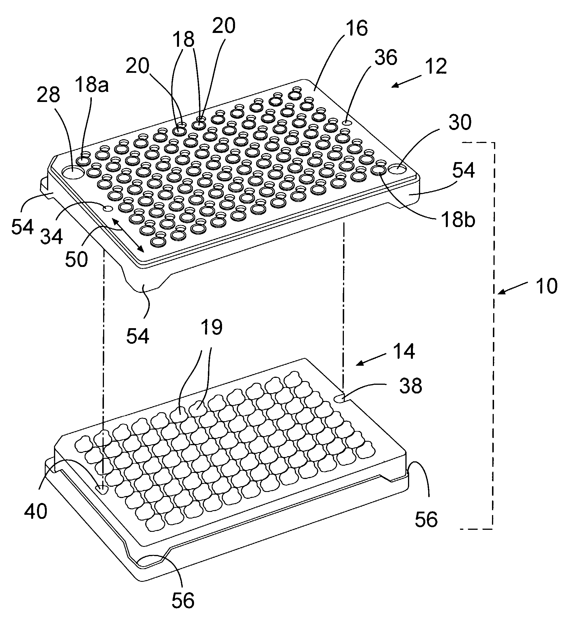
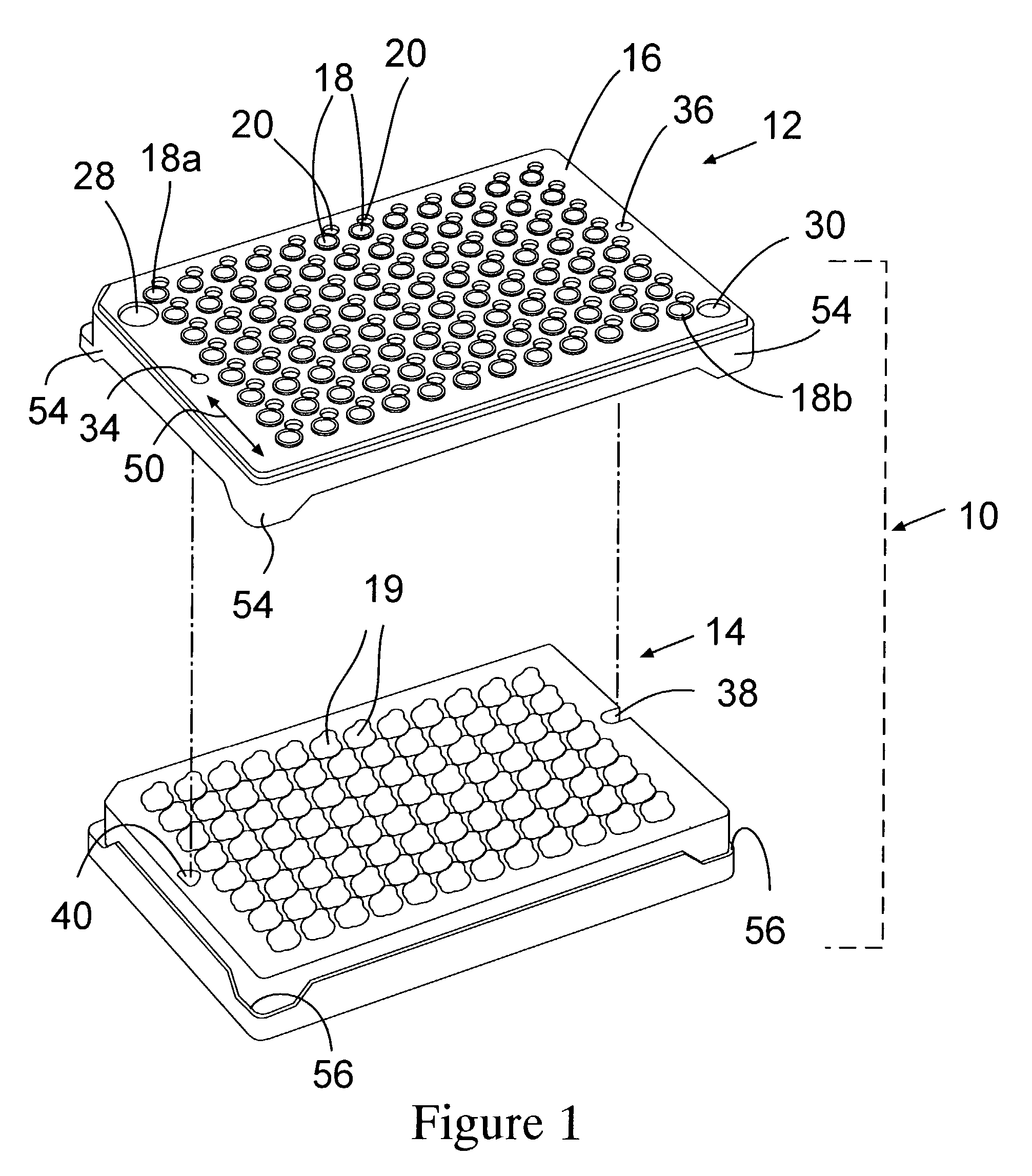
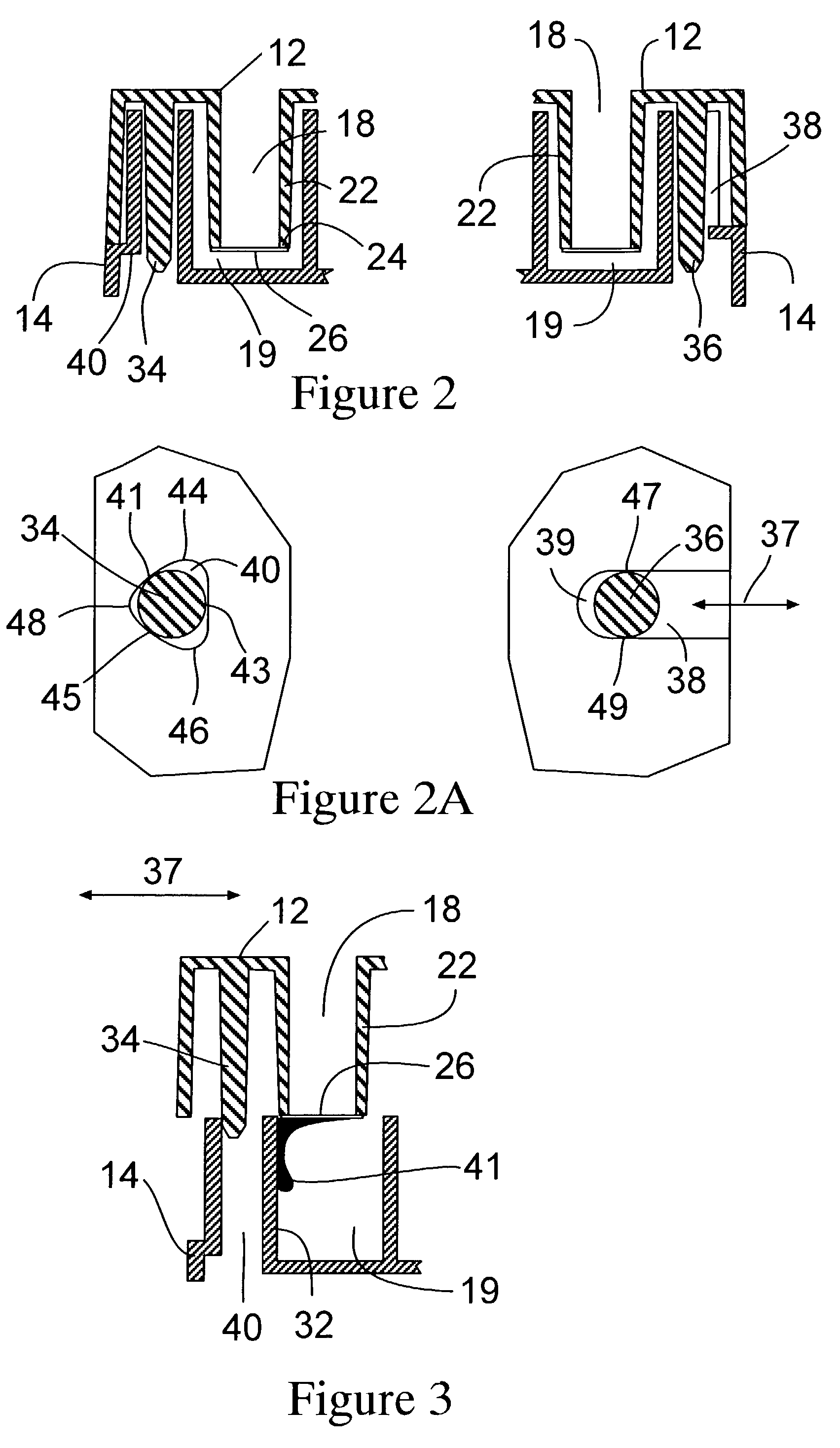
[0018]Referring to FIG. 1, a first embodiment of the multiwell test apparatus 10 of this invention comprises a multiwell filter plate 12 and a multiwell receiver plate 14. The multiwell filter plate 12 includes a plate 16 having a plurality of wells 18, each of which is paired with an access hole 20. The access holes 20 permit access through plate 16 to wells 19 of multiwell receiver plate 14 with a liquid handling device such as a syringe, cannula, pipette or the like. Each well 18 comprises a hollow, preferably tubular, member 22 and having a lower opening 24 to which is secured a permeable barrier 26...


PUM

PropertyMeasurementUnit
perimeteraaaaaaaaaa
permeableaaaaaaaaaa
concentrationaaaaaaaaaa

Abstract

A multiwell test apparatus comprising a multiwell filter plate and having wells that fit within the wells of a single or multiwell receiver plate is provided. The multiwell filter plate also is provided with posts which fit into holes of the receiver plate. The posts and holes are shaped to fix the position of the wells of the multiwell filter plate within the well(s) of the receiver plate and to permit controlled lateral movement of the multiwell filter plate when it is partially removed from the receiver plate so that excess liquid on the wells of the multiwell filter plate can be directed into the well(s) of the receiver plate.

Description

BACKGROUND OF THE INVENTION[0001]This invention relates to a multiwell test apparatus suitable for promoting fluid interactions such as by monitoring cell metabolism within wells of the test apparatus. More particularly, this invention relates to such a multiwell test apparatus comprising a multiwell filter plate and a receiver plate which permits adding or removing liquid from the receiver plate without disturbing a material such as cells within the wells of the multiwell filter plate.[0002]At the present time, multiwell test apparatus for testing samples include a multiwell filter plate, a feeding tray, a multiwell receiver plate and a lid. The wells of the multiwell filter plate are formed of a hollow, typically tubular, member with an open end to which is attached a membrane such as a microporous membrane. The tubular members can be inserted into a feeding tray containing a nutrient medium so that cells in the wells can be attached to the membrane and grown thereon. The cells ar...

Claims


Application Information

Patent Timeline
Patent Type & Authority Patents(United States)
IPC IPC(8): B01L11/00G01N1/28B01J4/00B01L3/00B01L9/00B01L99/00C12M1/12
CPCC12M23/12B01L3/50255B01L9/523B01L3/5025B01L2200/0642B01L2300/0829B01L2400/0457Y10T436/2575B01L2200/025
Inventor DESILETS, KENNETHRISING, DONALD
Owner MILLIPORE CORP
Why Eureka
Try Eureka