Image forming method using photothermographic material

a technology of photothermographic material and image forming system, which is applied in the direction of photosensitive materials, photo-taking processes, instruments, etc., can solve the problems of insufficient image quality of medical images in the general image forming system, and the level at which the digital recording imaging material can replace the medical silver salt film processed by conventional wet development, and the effect of increasing fog

Inactive Publication Date: 2006-11-14
FUJIFILM HLDG CORP +1
View PDF13 Cites 1 Cited by
  • Summary
  • Abstract
  • Description
  • Claims
  • Application Information

AI Technical Summary

Benefits of technology

[0210]The method of mixing the silver halide and the organic silver salt can include a method of mixing a separately prepared photosensitive silver halide and an organic silver salt by a high speed stirrer, ball mill, sand mill, colloid mill, vibration mill, or homogenizer, or a method of mixing a photosensitive silver halide completed for preparation at any timing in the preparation of an organic silver salt and preparing the organic silver salt. The effect of the invention can be obtained preferably by any of the methods described above.
[0212]In the invention, the time of adding silver halide to the coating solution for the image forming layer is preferably in the range from 180 minutes before to just prior to the coating, more preferably, 60 minutes before to 10 seconds before coating. But there is no restriction for mixing method and mixing condition as far as the effect of the invention appears sufficient. As an embodiment of a mixing method, there is a method of mixing in the tank controlling the average residence time to be desired. The average residence time herein is calculated from addition flux and the amount of solution transferred to the coater. And another embodiment of mixing method is a method using a static mixer, which is described in 8th edition of “Ekitai kongou gijutu” by N. Harnby and M. F. Edwards, translated by Kouji Takahashi (Nikkankougyou shinbunsya, 1989).2. Organic Silver Salt
[0213]The non-photosensitive organic silver salt particle according to the invention is relatively stable to light but serves as to supply silver ions and forms silver images when heated to 80° C. or higher under the presence of an exposed photosensitive silver halide and a reducing agent. The organic silver salt may be any organic material containing a source capable of reducing silver ions. Such non-photosensitive organic silver salt is disclosed, for example, in JP-A No. 10-62899 (paragraph Nos. 0048 to 0049), EP-A No. 0803764 A1 (page 18, line 24 to page 19, line 37), EP-A No. 0962812 A1, JP-A Nos. 11-349591, 2000-7683, and 2000-72711, and the like. A silver salt of organic acid, particularly, a silver salt of long chained fatty acid carboxylic acid (number of carbon atoms having 10 to 30, preferably, 15 to 28) is preferable. Preferred examples of the silver salt of the organic acid can include, for example, silver behenate, silver arachidinic acid, silver stearate, silver oleate, silver laurate, silver capronate, silver myristate, silver palmitate and mixtures thereof. Among the organic silver salts, it is preferred to use an organic silver salt with the silver behenate content of 50 mol % or more, particularly preferably, 75 mol % to 98 mol %.
[0214]There is no particular restriction on the shape of the organic silver salt usable in the invention and it may needle-like, bar-like, plate-like or flaky shape.
[0215]In the invention, a flaky shaped organic silver salt is preferred. In the present specification, the flaky shaped organic silver salt is defined as described below. When an organic acid silver salt is observed under an electron microscope, calculation is made while approximating the shape of an organic acid silver salt particle to a rectangular body and assuming each side of the rectangular body as a, b, c from the shorter side (c may be identical with b) and determining x based on numerical values a, b for the shorter side as below.x=b / a
[0216]As described above, x is determined for the particles by the number of about 200 and those capable of satisfying the relation: x (average)≧1.5 as an average value x is defined as a flaky shape. The relation is preferably: 30≧=x (average)≧=1.5 and, more preferably, 15≧x (average)≧1.5. By the way, needle-like is expressed as 1≦=x (average)≦1.5.

Problems solved by technology

While various kinds of hard copy systems using a pigment and a dye such as an ink-jet printer or electrophotography have been distributed as a general image forming system using such a digital recording imaging material, images in the digital recording imaging material obtained by such a general image forming system are insufficient in terms of image qualities required for medical images.
However, digital recording imaging material has not reached a level at which it can replace medical silver salt film processed by conventional wet development.
Since such a photothermographic system using an organic silver salt has no fixing step and the photosensitive material contains all chemicals necessary for image forming, there has been an intrinsic problem in raw preservability, that is, “increase in fog”, in which an unexposed portion is blackened during storage from manufacture of a photosensitive material until the material is actually put into use, and another intrinsic problem of “print-out”.
While such a photothermographic material using a silver halide with a high silver iodide content is a remarkable material in its ability for preventing the generation of fogging and print out, there has been a problem in that the photothermographic material is generally low in sensitivity.
However, these pigments and dyes may unfavorably color the layer, and turbidity of the layer may be increased.
It is not preferable to largely increase the incidence angle of the laser beam due to the problem of ghosts, which appear due to surface reflection of the laser beam, as well as the problem of blurring of the image.
Since the laser beam can only be tilted within a limited range, the effect of improving the interference fringe has inevitably been restricted.
With respect to the blue laser diode as well, it is a crucial problem to prevent the interference fringe from being generated.

Method used


Image

  • Image forming method using photothermographic material
  • Image forming method using photothermographic material
  • Image forming method using photothermographic material

Examples


example 1

[0434](Preparation of PET Support)

[0435]PET having IV (intrinsic viscosity) of 0.66 (measured in phenol / tetrachloroethane=6 / 4 (weight ratio) at 25° C.) was obtained according to a conventional manner using terephthalic acid and ethylene glycol. The product was pelletized, dried at 130° C. for 4 hours, melted at 300° C. Thereafter, the mixture was extruded from a T-die and rapidly cooled to form a non-tentered film having such a thickness that the thickness should become 175 μm after tentered and thermal fixation.

[0436]The film was stretched along the longitudinal direction by 3.3 times using rollers of different peripheral speeds, and then stretched along the transverse direction by 4.5 times using a tenter machine. The temperatures used for these operations were 110° C. and 130° C., respectively. Then, the film was subjected to thermal fixation at 240° C. for 20 seconds, and relaxed by 4% along the transverse direction at the same temperature. Thereafter, the chucking part was slit...


PUM

PropertyMeasurementUnit
wavelengthaaaaaaaaaa
angleaaaaaaaaaa
grain sizeaaaaaaaaaa

Abstract

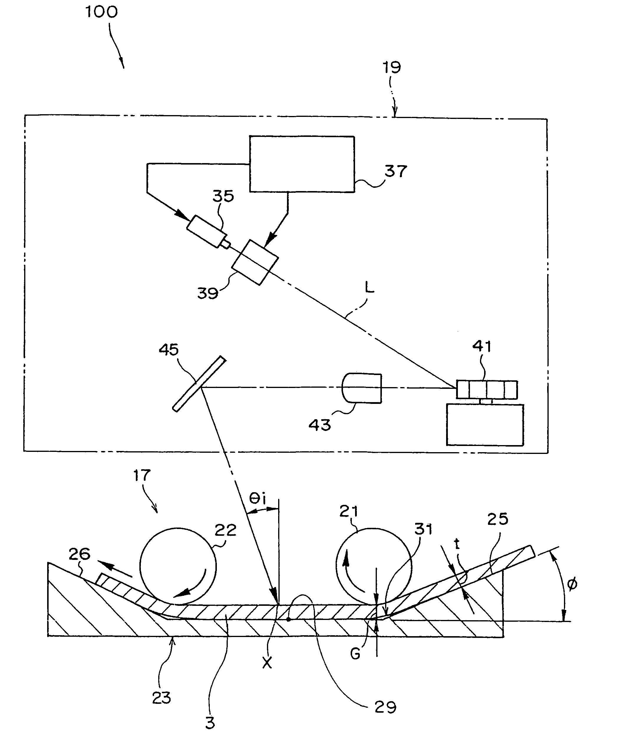
An image forming method for forming an image by exposing a photothermographic material to a laser beam, the laser beam being a laser diode beam having a peak light-emission intensity at a wavelength of 350 nm to 450 nm. The photothermographic material comprises at least a non-photosensitive silver salt, a photosensitive silver halide, a binder and a reducing agent, wherein a silver iodide content of the photosensitive silver halide is 40% by mole or more. The image forming method comprises the steps of:A) conveying the photothermographic material; andB) exposing the photothermographic material to the laser beam by scanning it in a main scanning direction while conveying the photothermographic material, wherein an angle between a plane extending in a normal direction of the photothermographic material including a straight line representing the main scanning direction and a plane extending in an incidence direction of the laser beam including a straight line representing the main scanning direction is 0° to 15°.

Description

CROSS-REFERENCE TO RELATED APPLICATION[0001]This application claims priority under 35 USC 119 from Japanese Patent Application Nos.2002-331091, and 2003-42975, the disclosures of which are incorporated by reference herein.BACKGROUND OF THE INVENTION[0002]1. Field of the Invention[0003]The present invention relates to an image forming method using a photothermographic material, particularly to an image forming method by exposing a photothermographic material including a silver halide emulsion having a high silver iodide content to light with an wavelength of 350 nm to 450 nm. The invention also relates to an image forming method for a photothermographic material which provides improvements with respect to uneven image density in a sub-scanning direction by suppressing generation of interference fringes.[0004]2. Description of the Related Art[0005]In the medical imaging field and the graphic arts field, there has been, in recent years, a strong desire for a dry photographic process fr...

Claims


Application Information

Patent Timeline
Patent Type & Authority Patents(United States)
IPC IPC(8): G03C1/498G03C1/035G03C5/26G03C1/10G03C5/08
CPCG03C1/49818G03C1/49881G03C1/10G03C1/49827G03C1/49845G03C1/49863G03C2200/24G03C2001/03558G03C2001/03594G03C2200/36G03C2200/39G03C2200/43Y10S430/146
Inventor NARIYUKI, FUMITOSHIKII, SHINICHIKOJIMA, TETSUYA
Owner FUJIFILM HLDG CORP
Why Eureka
Try Eureka