Photothermographic material and image forming method

Inactive Publication Date: 2006-04-13
FUJIFILM CORP +1
View PDF5 Cites 6 Cited by
  • Summary
  • Abstract
  • Description
  • Claims
  • Application Information

AI Technical Summary

Benefits of technology

[0023] The photothermographic material according to the invention preferably comprises a development accelerator, is preferably exposed by a laser beam, especially by a laser beam having a wavelength of 350 nm to 450 nm, whereby high effects of the invention can be obtained. The photothermographic material is preferably developed at a temperature in a range of 100° C. to 140° C. for 12 sec or less, and the photothermographic material is preferably developed at a line speed of 23 mm / sec or higher. As a result, higher effects of the invention can be obtained. The constitutions and preferable components of the above-mentioned layers will be described in detail below.

Problems solved by technology

However, the use of the silver iodide emulsion has caused new problems which must be solved.
One problem is that the color tone of developed silver images is unsettled and changes due to a slight variation in the temperature of thermal development.
Another problem is that there is a difference in color tone among parts of a developed sheet.
Especially when, the photothermographic material is used as an image recording material for medical diagnosis, the color tone of a developed silver image influences diagnostic ability, and therefore, the problems are serious.

Method used


Image

  • Photothermographic material and image forming method
  • Photothermographic material and image forming method
  • Photothermographic material and image forming method

Examples


example 1

1. Preparation of PET Support

1) Film manufacturing

[0417] PET having IV (intrinsic viscosity) of 0.66 (measured in phenol / tetrachloroethane=6 / 4 (weight ratio) at 25° C.) was obtained according to a conventional manner using terephthalic acid and ethylene glycol. The product was pelletized, dried at 130° C. for 4 hours. Thereafter, the mixture was extruded from a T-die and rapidly cooled to form a non-tentered film having such a thickness that the thickness should become 175 μm after tentered and thermal fixation.

[0418] The film was stretched along the longitudinal direction by 3.3 times using rollers of different peripheral speeds, and then stretched along the transverse direction by 4.5 times using a tenter machine. The temperatures used for these operations were 110° C. and 130° C., respectively. Then, the film was subjected to thermal fixation at 240° C. for 20 seconds, and relaxed by 4% along the transverse direction at the same temperature. Thereafter, the chucking part was...

example 2

[0500] The sample Nos. 1 to 20 of Example 1 were exposured and thermally developed as described below, and sensitivity difference, Dmax difference and difference in color tone of the obtained images were evaluated.

[0501]

[0502] Exposure was performed on samples using a Fuji medical dry laser imager FM-DP L in which a NLHV 3000E laser diode fabricated by Nichia Corporation as a laser diode beam source was mounted in an exposure portion thereof and a beam diameter thereof was adjusted to about 100 μm. Other exposure conditions were as follows: exposure of a photothermographic material was performed for 10−6 sec with a photothermographic material surface illumination intensity at 0 mW / mm2 and at various values from 1 mW / mm2 to 1000 mW / mm2. A light-emission wavelength of laser beam was 405 nm. Thermal development was performed in conditions that 4 panel heaters were set to 117° C.-117° C.-117° C.-117° C., and developed for 12 seconds by controlling the transport speed. And further, anot...

example 3

1. Preparation of Photothermographic Materials

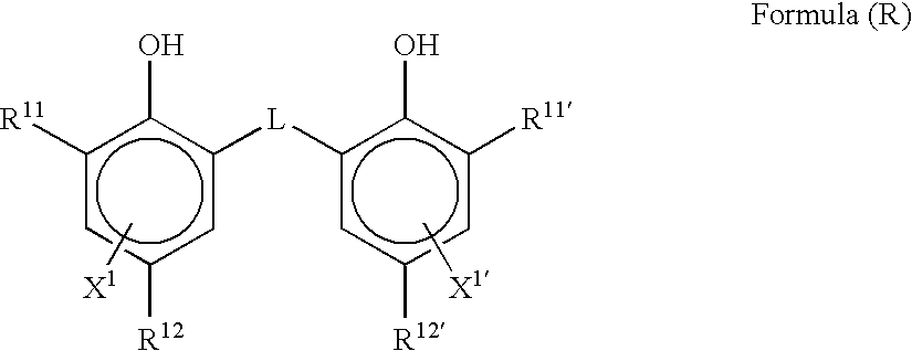
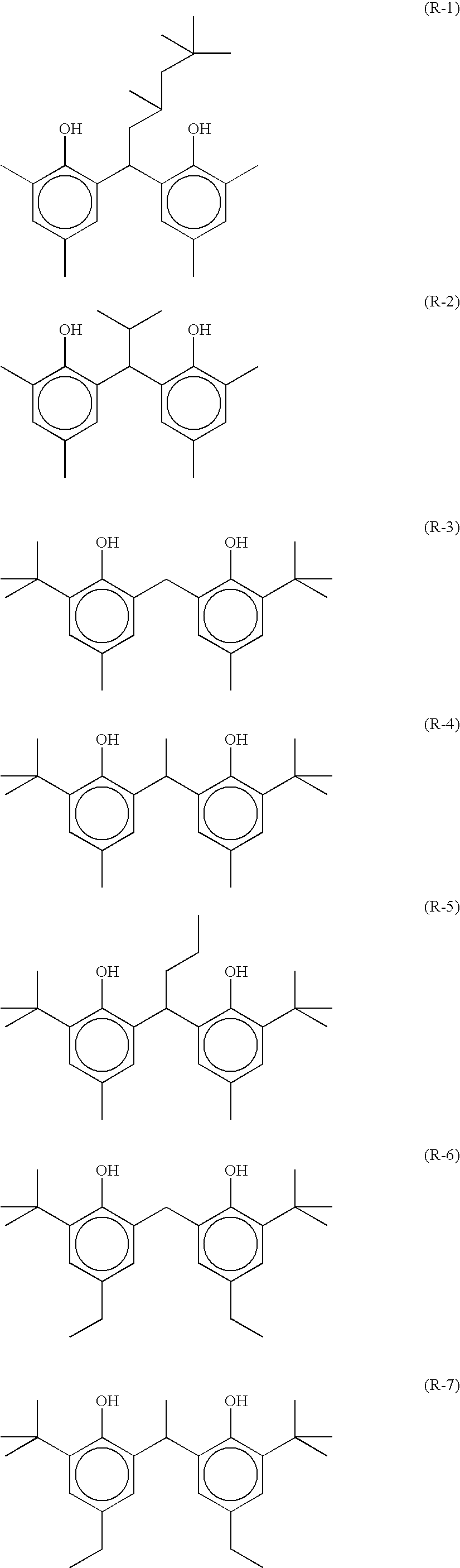
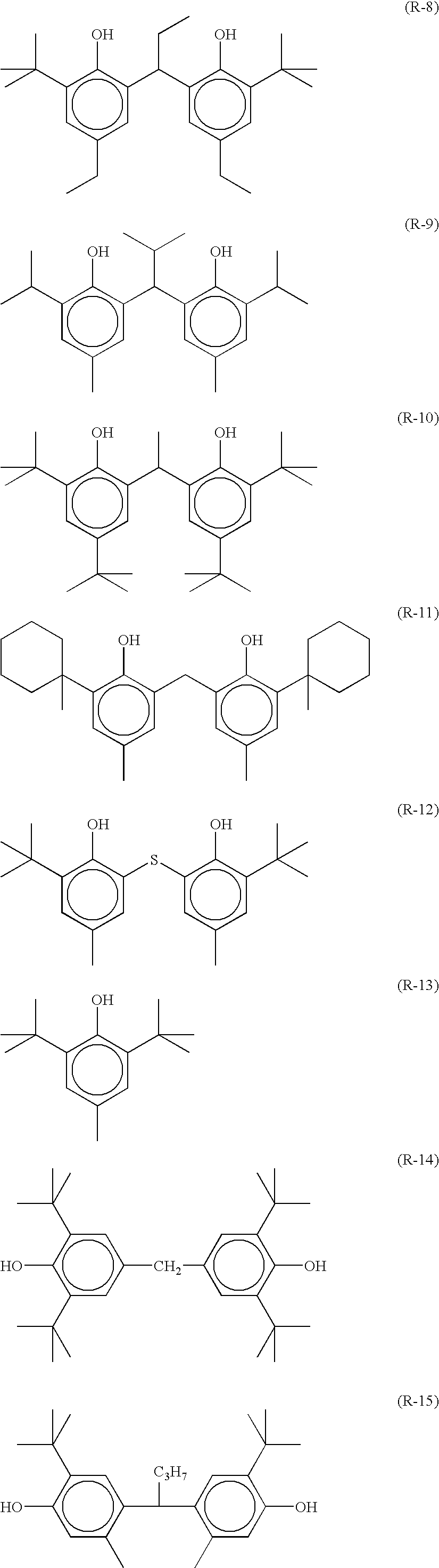
[0511] Samples a to k were prepared as similar to Example 1 but reducing agent-1 (R-6) and reducing agent-2 (R-5) were changed to compounds as shown in Tables 3 and 4. Compounds involved in claim 7 and 10 in present invention were represented as compound A in the tables. Compounds involved in claim 8 and 11 in present invention were represented as compound B in the tables. Compounds involved in claim 9 and 12 in present invention were represented as compound C in the tables.

2. Evaluation of the Samples

[0512] Samples above prepared were imagewise exposed and thermal developed using a Fuji medical dry laser imager FM-DPL similarly to Example 1, wherein the imagewise exposure was started from a leading end of the photothermographic material followed by the thermal development which was started before completing the imagewise exposure up to a posterior end thereof.

[0513] Sensitivity difference (A S) and density difference (A Dmax) in e...


PUM


Abstract

A photothermographic material including, on at least one surface of a support, at least a photosensitive silver halide containing a silver iodide at 40 mol % or more, a non-photosensitive organic silver salt, and a reducing agent, wherein the photothermographic material contains two or more kinds of the reducing agent at the mixing ratio to satisfy at least one of a), b), c) and d): a) a difference between a sensitivity or b) a difference between a maximum density is 0.10 or less, when developed at 120° C. for 10 sec and a sensitivity when developed at 120° C. for 14 sec; c) a difference between a sensitivity or d) a difference between a maximum density is 0.10 or less, when developed at 117° C. for 12 sec and a sensitivity when developed at 123° C. for 12 sec. An image forming method using the photothermographic material is also provided.

Description

CROSS-REFERENCE TO RELATED APPLICATION [0001] This application is a continuation-in-part of earlier filed application Ser. No. 10 / 191,485, which claims priority under 35 USC 119 from Japanese Patent Application Nos. 2001-212445, 2001-227838, 2001-346122, and 2001-349031, and is a continuation-in-part of earlier filed application Ser. No. 10 / 825,102, which claims priority under 35 USC 119 from Japanese Patent Application No. 2003-119775, the disclosure of which is incorporated by reference herein.BACKGROUND OF THE INVENTION [0002] 1. Field of the Invention [0003] The present invention relates to a photothermographic material and a method of forming an image using the photothermographic material. More particularly, the invention relates to an improved photothermographic material, which exhibits stable photographic properties without unevenness in density, and an improved method of forming an image. [0004] 2. Description of the Related Art [0005] In recent years, it has been strongly d...

Claims


Application Information

Patent Timeline
IPC IPC(8): G03C1/00
CPCG03C1/49818G03C1/49827G03C1/49845G03C1/49881G03C7/30541G03C2001/03558G03C2200/39G03C2200/52G03C2200/60
Inventor YOSHIOKA, YASUHIROYAMANE, KATSUTOSHIGOTO, YASUHIKO
Owner FUJIFILM CORP
Why Eureka
Try Eureka