Electro-optical sensing device with reference channel

a technology of optical sensing and reference channels, applied in the direction of fluorescence/phosphorescence, instruments, material analysis, etc., can solve the problems of inability to know which of the plots to use, covalent and permanent alteration of the indicator molecular structure, and difficult measurement of the first variable (i.e., analyte concentration)

Active Publication Date: 2006-11-14
SENSEONICS INC
View PDF169 Cites 86 Cited by
  • Summary
  • Abstract
  • Description
  • Claims
  • Application Information

AI Technical Summary

Benefits of technology

[0026]A first aspect of the present invention is generally characterized in an electro-optical sensing device for detecting the presence and concentration of an analyte in an ambient fluid (i.e., liquid or gaseous medium) including a pair of indicator elements positioned to receive excitation radiation from a radiation source and to transmit resultant radiation to a pair of photosensitive elements. The indicator elements each contain indicator molecules having an optical characteristic responsive to the presence of an analyte; however, one of the indicator elements is covered by an analyte-impermeable chamber that renders the indicator element insensitive to the presence of the analyte in the external environment so that it can be used as a reference to cancel environmental and systemic variables that affect both indicator elements. The chamber preferably holds an analyte-containing fluid in contact with the reference indicator element so that the indicator elements operate under nominally identical conditions. The indicator element used to measure the analyte in the external medium is preferably also covered, but in a manner that provides direct contact between the analyte and the indicator element.
[0033]Some of the advantages of the present invention over the prior art include increased accuracy, enhanced mechanical protection of the indicator elements, ease of manufacturing, and prevention of contamination including condensation.

Problems solved by technology

Introduction of a second variable such as temperature thus makes measurement of the first variable (i.e., analyte concentration) much more difficult.
This degradation reaction results in the covalent and permanent alteration of the indicator molecular structure.
It is not possible to know which of the plots to use for finding oxygen concentration without knowledge of the temperature and the amount of degradation experienced by the sensor.
Yet another example of error that may be introduced is from variable excitation light levels.
Since the excitation light source directly “pumps” the fluorescence detected from the indicator, any fluctuation or degradation in the source light will directly be introduced as error into the calibration.
Light source drift can be caused by transient changes in the sensor power supply or due to simple operational life degradation in the light source itself.
These influential factors can become complex and are highly interdependent.
For example, an increase in temperature will also tend to increase the rate of degradation due to photo-oxidation.
The result is a very complex and difficult to understand series of interdependent variables that directly affect the accuracy of a measurement by an electro-optical sensing device.
This approach, however, may induce other differences between the channels that cannot be canceled by taking the ratio of the outputs.
It can be seen that the ratio of the signal and reference channel outputs is not a flat line as desired, but an increasing function that makes interpretation of the results complex.

Method used


Image

  • Electro-optical sensing device with reference channel
  • Electro-optical sensing device with reference channel
  • Electro-optical sensing device with reference channel

Examples


Embodiment Construction

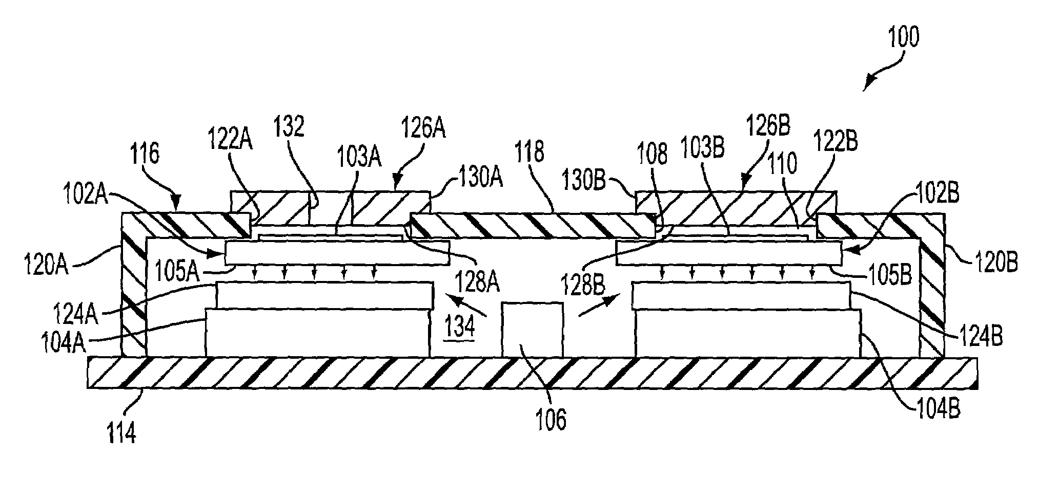
[0044]An electro-optical sensing device 100 according to the present invention is illustrated in FIGS. 6 and 7. Sensing device 100 generally includes a signal channel with an indicator element 102A and a photosensitive element 104A, a reference channel with an indicator element 102B and a photosensitive element 104B, and a radiation source 106 providing excitation radiation for both the signal and reference channels. The indicator elements 102A and 102B each include an indicator layer or membrane containing indicator molecules having one or more optical characteristics that are affected by the local presence of an analyte. The indicator membrane 103A of the signal channel is exposed to an exterior of the device and is thus responsive to the local presence of an analyte in the external environment or medium. The indicator membrane 103B of the reference channel is covered and is thus not responsive to the local presence of an analyte in the external environment. Since the membranes ar...


PUM

PropertyMeasurementUnit
reflectanceaaaaaaaaaa
photosensitiveaaaaaaaaaa
opticalaaaaaaaaaa

Abstract

An electro-optical sensing device for detecting the presence and concentration of an analyte in a liquid or gaseous medium includes a pair of indicator elements positioned to receive radiation from a radiation source and transmit radiation to a pair of photosensitive elements. The indicator elements each contain indicator molecules having an optical characteristic responsive to the presence of an analyte; however, one of the indicator elements is covered by an analyte-impermeable chamber that renders the indicator element insensitive to the presence of the analyte in the medium outside the chamber so that it can be used as a reference to cancel environmental and systemic variables that affect both indicator elements. The chamber preferably holds an analyte-containing fluid in contact with the reference indicator element so that the indicator elements operate under nominally identical conditions. The indicator element used to measure the analyte in the external medium is preferably also covered, but in a manner that provides direct contact between the analyte and the indicator element.

Description

RELATED APPLICATION[0001]This patent application claims priority of provisional patent application 60 / 288,498, filed May 4, 2001.BACKGROUND OF THE INVENTION[0002]1. Field of the Invention[0003]The invention relates to electro-optical sensing devices for detecting the presence or concentration of an analyte in a liquid or gaseous medium. More particularly, the invention relates to an electro-optical sensing device having a signal channel responsive to the presence of an analyte in a liquid or gaseous medium and a reference channel that is not responsive to the presence of the analyte in the medium.[0004]2. Discussion of the Background Art[0005]U.S. Pat. No. 5,517,313, the disclosure of which is incorporated herein by reference, describes an electro-optical sensing device that detects the presence and amount of an analyte using fluorescence of an indicator molecule. Broadly speaking, in the context of the field of the present invention, indicator molecules are molecules having one or ...

Claims


Application Information

Patent Timeline
Patent Type & Authority Patents(United States)
IPC IPC(8): G01N21/00G01N21/64G01N21/77G01N21/78
CPCG01N21/6428G01N21/77G01N21/783Y10T436/144444G01N2021/7786G01N2021/7793G01N2021/7796G01N2021/6432
Inventor COLVIN, JR., ARTHUR E.LYNN, ROBERT W.
Owner SENSEONICS INC
Why Eureka
Try Eureka