Engine decarbonizing fluids

a technology of engine and fluid, applied in the field of engine decarbonizing fluid, can solve the problems of consuming a lot of fuel, and destroying valves and even pistons, etc., and achieves the effects of convenient transportation, convenient operation, and thorough cleaning

Inactive Publication Date: 2006-11-14
BOWSMAN SHELBA F +1
View PDF7 Cites 13 Cited by
  • Summary
  • Abstract
  • Description
  • Claims
  • Application Information

AI Technical Summary

Benefits of technology

[0018]Accordingly, several objects and advantages of this invention are that this invention and process requires no dismantling of the engine. Further the attachments make it possible to perform the process on a wide variety of engines. This is done because a mechanism is used which pressurizes the chemical and results in a very thorough cleaning.
[0019]Other objects and advantages include a small and compact tool cabinet which makes it easily transportable. A further object and advantage is that the cabinet has a 9-foot hose which allows the chemical to be remote from the engine being serviced. Further, the process is easy to perform and successfully removes the contamination.
[0020]Additional objects and advantages involve the energy source for the invention, which operates by using pressurized air. Therefore, no electrical connections are necessary.
[0021]The regulator, on / off valve and pressure gauge have no chemical traveling through them. This prevents their rapid destruction. Further, this invention has incorporated a sight glass, on / off product control valve, strainer and quick disconnect in order to make it versatile to connect multiple attachments for various types and sizes of engines.
[0022]It is a further object of this invention to provide an engine decarbonizing system comprising a manifold with one central and four lateral bores. Pressurized air and decarbonizing fluid in separate containers are adapted to be co-mingled and fed to and through the manifold. A tube assembly has an output tube and two parallel input tubes operatively coupled. The output tube is coupled to the central bore and the two parallel input tubes are coupled to the containers for dispensing pressurized decarbonizing fluid. Four short tubes are coupled to the lateral bores and second ends have a rigid cylindrical nozzle selectively positionable within a spark plug for the delivery of a spray of pressurized decarbonizing fluid. Four switches are coupled to the manifold adjacent to the interface between a short tube and a short bore for selectively allowing or precluding the flow of decarbonizing fluid.
[0023]Still further objects and advantages will become apparent from a consideration of the ensuing description and accompanying drawings.

Problems solved by technology

However, it requires the disassembly of the various engine parts, which is expensive and time consuming.
Automotive emissions are considered a major contributor to air pollution.
Unfortunately, a spread of ratios like that can burn too much fuel if the mixture is too rich, destroy valves and even pistons if it is too lean, and reduce power if the mixture is too far on the other side of the best ratio and create clouds of pollution.
It is because of this that the carburetor is inferior to the more sophisticated fuel injection system.
The problems arise as a result of regular day to day driving which creates a buildup of contaminants in the fuel and air intake systems.
This buildup can cause various problems with the engine such as rough idling, engine run on, hesitating, surging, stalling, pinging, knocking, misfiring, poor gas mileage, toxic emissions and general bad performance and driveability.
These elements are required for an engine to operate, however, contaminants begin building up as the engine operates.
These are the carbon and combustion deposits that automotive technicians work hard to remove from the upper engine area and finding it difficult-to-impossible to do.
Previously, in order to remove such deposits, mechanics would have to either use chemicals which would only superficially and temporarily clean the engine (U.S. Pat. No. 4,787,348 to Timothy A. Taylor and assigned to Parker Automotive Corporation) or run cleaner through the rail and fuel injectors by disabling the electric fuel pump, a process which is time consuming and only cleans the fuel rail, fuel injectors and the intake valves.
This is extremely difficult, very time consuming, and costly.

Method used


Image

  • Engine decarbonizing fluids
  • Engine decarbonizing fluids
  • Engine decarbonizing fluids

Examples


Embodiment Construction

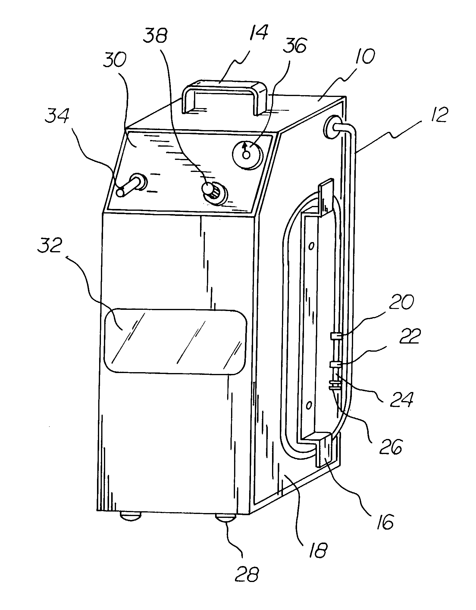
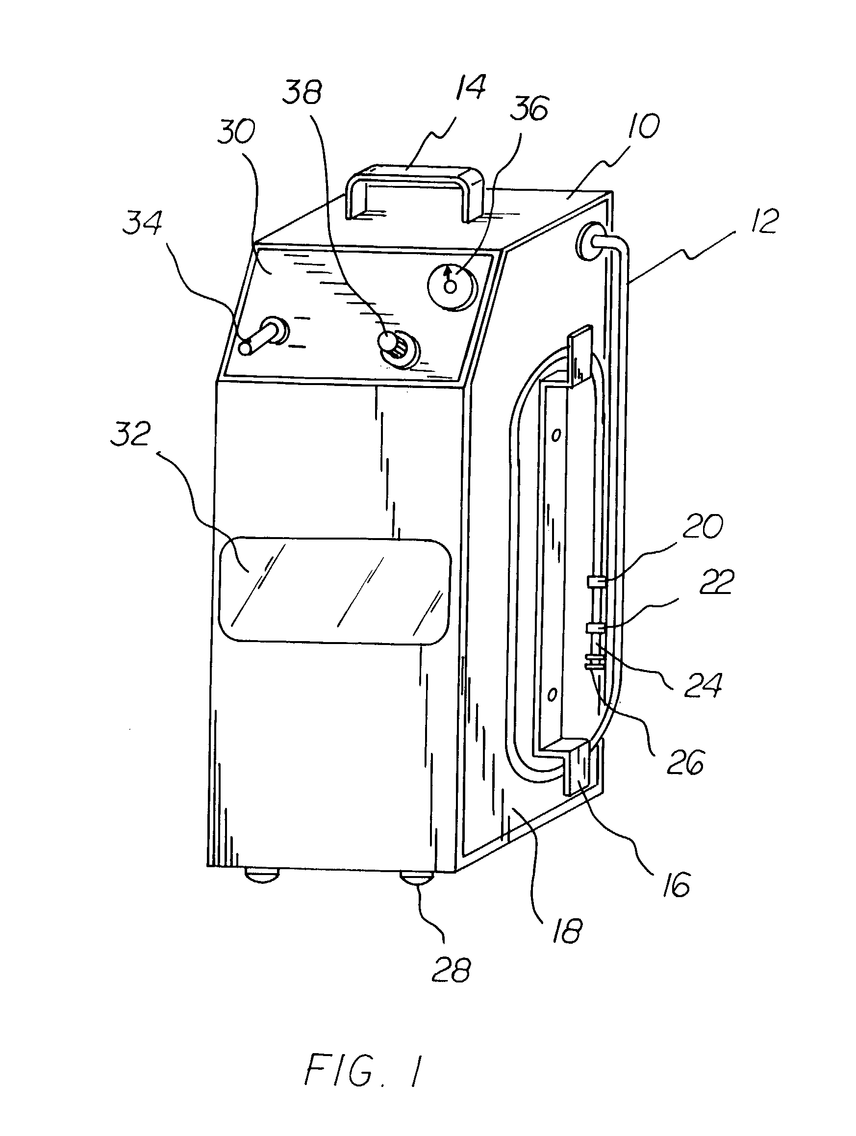
[0052]An embodiment of the machine for the invented fluids is depicted in FIG. 1. It shows the exterior features of the machine. The exterior is painted with a powder coat paint, FIG. 1 (10), which insures a longer lasting visually appealing machine due to the fact that the exterior will be resistant to damage from the chemicals used.

[0053]A name plate, FIG. 1 (32), is made out of lexan which is resistant to the chemicals used in the process.

[0054]A control panel, FIG. 1 (30), is covered with lexan to assure longer durability and resistant to the chemical used in the process.

[0055]The side of the machine from where a hose, FIG. 1 (12), extends is covered with a side panel of lexan, FIG. 1 (18), for durability.

[0056]A handle, FIG. 1 (14), is made of chrome and angled. The placement of the handle insures balance when the machine is picked up. Due to the size, shape and weight of the machine, the placement of the handle assures easy mobility and stability of the machine.

[0057]A bracket...


PUM

PropertyMeasurementUnit
air pressureaaaaaaaaaa
obtuse angleaaaaaaaaaa
weightaaaaaaaaaa

Abstract

Fluids for cleaning and decarbonizing internal combustion engines include a fuel system and injector cleaner fluid to be added to the fuel tank, an engine oil supplement to be added to the oil crank case, an aerosol air intake cleaner to be aerosol sprayed into the air intake system and throttle body then scrubbed, an air induction cleaner and decarbonizer to be injected by sprayers while the engine is running, and a piston and ring cleaner fluid for cleaning and decarbonizing internal combustion engines.

Description

RELATED APPLICATIONS[0001]This application is a continuation in part application of application Ser. No. 09 / 784,742 filed Feb. 15, 2001 now U.S. Pat. No. 6,564,814 which is a continuation in part of abandoned application Ser. No. 09 / 777,218 filed Feb. 5, 2001, which is, in turn a continuation in part of application Ser. No. 09 / 515,561 filed Feb. 29, 2000 which issued Dec. 10, 2002 as U.S. Pat. No. 6,491,044 entitled “Thorough Air Induction, Fuel Injection And Decarbonization Cleaning Machine And Process That Requires No Disassembly of The Engine or Its Components Which Uses Compressed Air as Its Source of Power” which is, in turn, a continuation in part of abandoned application Ser. No. 08 / 862,376 filed May 23, 1997.CROSS REFERENCES TO RELATED APPLICATIONS[0002]The fluid and machine requires the use of an attachment determined by the type of engine being serviced. Additionally, there are some engines that cannot accept the chemical directly from the machine itself. An apparatus acco...

Claims


Application Information

Patent Timeline
Patent Type & Authority Patents(United States)
IPC IPC(8): C11D7/50F02B77/04F02M35/10F02M65/00
CPCC10L1/143C10L10/06F02B77/04F02B77/083F02M25/00F02M35/10137F02M35/10216F02M65/007C10L1/1616C10L1/1985C10L1/2383C10M2203/1006C10M2205/028C10M2219/044C10M2219/046C10N2230/04C10N2240/10F01M9/02F02M35/10C10L2300/30C10N2030/04C10N2040/25Y02A50/2351
Inventor BOWSMAN, SHELBA F.COSENTINO, PETER
Owner BOWSMAN SHELBA F
Why Eureka
Try Eureka