Power supply and method for regulating supply voltage

Active Publication Date: 2006-11-14
INFINEON TECH AUSTRIA AG
View PDF11 Cites 32 Cited by
  • Summary
  • Abstract
  • Description
  • Claims
  • Application Information

AI Technical Summary

Benefits of technology

[0010]Preferred embodiments of the invention may provide a switched mode power supply and a power controller for a switched mode power supply, which mitigate or substantially overcome the problems of known power supplies

Problems solved by technology

Primarily, this type of self-supply power is quite inefficient because the power controller IC is always powered by the controllable power source, which is coupled to the high bus voltage (usually around 400V), and power consumption in the self-supply power source is quite high.
Additionally, the high power consumption may cause thermal problems for the controlle

Method used


Image

  • Power supply and method for regulating supply voltage
  • Power supply and method for regulating supply voltage
  • Power supply and method for regulating supply voltage

Examples


Example

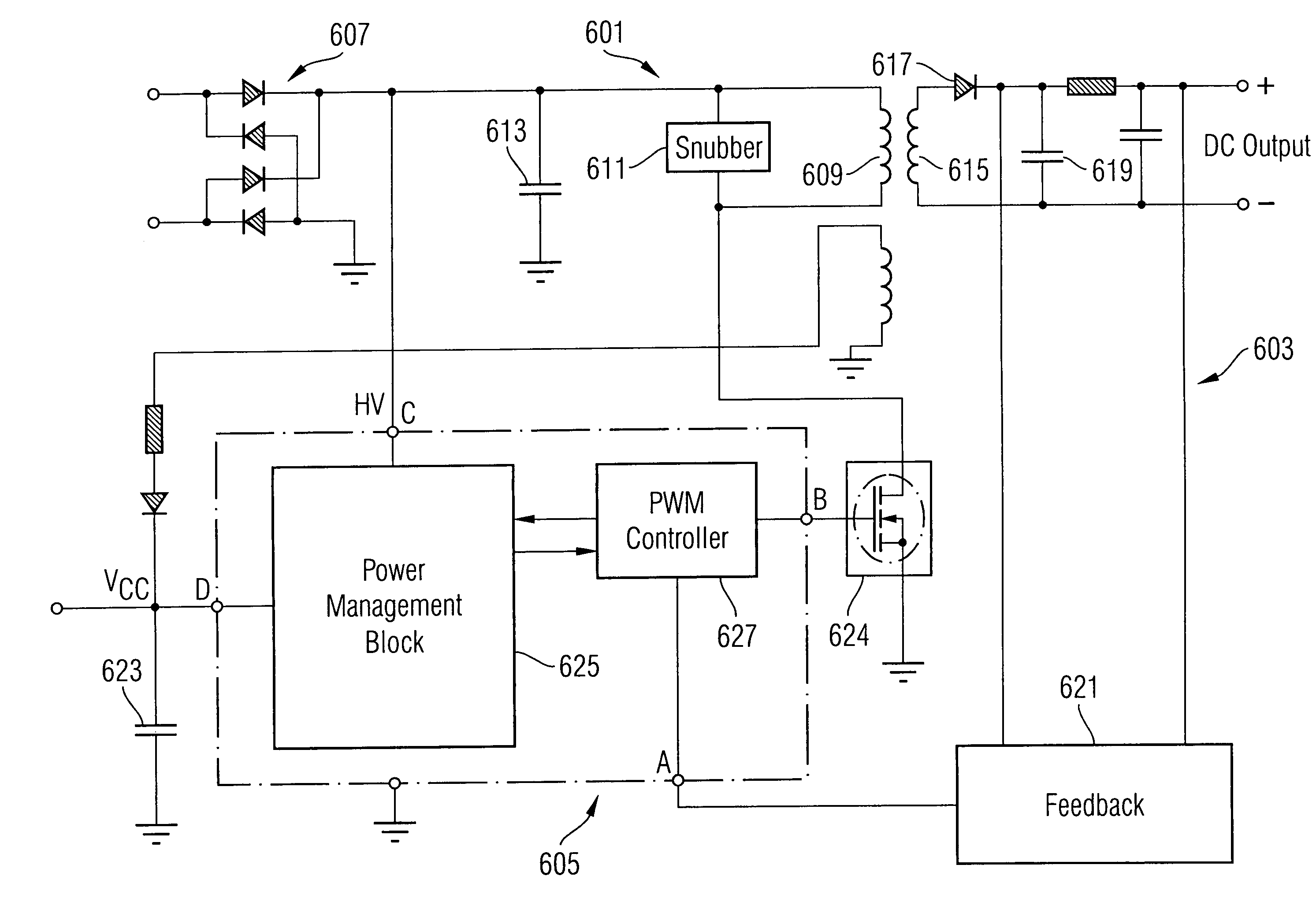
[0049]A preferred embodiment of the invention will now be described, by way of example only, with reference to FIGS. 6 to 10, of which:

[0050]FIG. 6 shows a switched mode power supply according to an embodiment of the invention. The power supply includes a primary side 601, a secondary side 603 and a power controller 605. The primary side 601 includes a DC power source 607 (shown in FIG. 6 as an AC power source, a rectifier and a capacitor 613 dropped to ground to smooth the rectified DC voltage), a primary inductive winding 609 coupled to the power source 607 at one end and to the power controller 605 at the other end, and a snubber circuit 611. The function of the snubber circuit will be discussed below. The secondary side 603 includes a secondary inductive winding 615 (coupled to the winding 609 on the primary side), a rectifier 617, a feedback capacitor 619 and a feedback circuit 621. The transformer also includes an auxiliary winding. A possible arrangement for the feedback circ...


PUM


Abstract

In a preferred embodiment, there is provided a switched mode power supply operable in start-up mode, normal mode and standby mode. The power supply may comprise a transformer having a primary winding on a primary side and a secondary winding on a secondary side, the primary winding being coupleable to a DC input voltage, and circuitry on the secondary side being arranged to provide a DC output voltage; and a power controller. The power controller may comprise a regulation controller for regulating a DC supply voltage on a supply line during standby mode, and a high voltage device coupled to the DC input voltage and the supply line. The current through the high voltage device to the supply line, during standby mode, may be controlled by the regulation controller. During standby mode, when the supply voltage is greater than or equal to a reference voltage, the current through the high voltage device to the supply line is substantially zero. When the supply voltage is less than the reference voltage, the greater the difference between the supply voltage and the reference voltage, the greater the current through the high voltage device to the supply line. In other preferred embodiments, there is also provided the power controller itself and a method for regulating a supply voltage during standby mode.

Description

TECHNICAL FIELD[0001]The invention relates to switched mode power supplies and methods for regulating supply voltage.BACKGROUND[0002]Many electronic devices use switched mode power supplies due to their higher power efficiency and smaller physical size compared to other types of power supply. Switched mode power supplies are also advantageous in that these supplies can provide regulated output voltages having magnitudes higher than or lower than the unregulated input supply and can also supply different outputs of different voltages.[0003]In a switched mode power supply system, a controller integrated circuit (IC) is used to generate the switching signal. To power the controller IC, different schemes can be found. U.S. Pat. No. 6,587,357, which is incorporated herein by reference, describes one known switched mode power supply system and method of powering the controller IC and is shown in FIG. 1. Referring to FIG. 1, the switched mode power supply includes a primary circuit portion...

Claims


Application Information

Patent Timeline
IPC IPC(8): H02M3/335H02M7/44
CPCH02M1/36H02M3/33523H02M2001/0032Y02B70/16H02M1/0032Y02B70/10
Inventor CHAN, TUCK MENGGONG, XIAOWUHU, JINGJEOH, MENG KIATLIM, KOK KEELUO, JUNYANG
Owner INFINEON TECH AUSTRIA AG
Why Eureka
Try Eureka