Method and apparatus for monitoring sensor performance during rate-responsive cardiac stimulation

a sensor and rate-responsive technology, applied in the field of implantable cardiac stimulation devices, can solve the problems of more oxygenated blood, fixed rate pacing, and insufficient activity signal to the control unit,

Inactive Publication Date: 2006-11-14
PACESETTER INC
View PDF14 Cites 67 Cited by
  • Summary
  • Abstract
  • Description
  • Claims
  • Application Information

AI Technical Summary

Benefits of technology

[0021]Another feature of the present invention is a sensor cross-check histogram in which sensor indicated rate differences are stored. Histogram data aids the clinician in selecting programmable operating parameters that control the calculation of sensor indicated rates and the rate response of the cardiac stimulation device.
[0022]The foregoing and other features of the present invention are realized by providing an implantable cardiac stimulation device equipped with data acquisition capabilities and two or more sensors that provide a signal related to metabolic demand. In a preferred embodiment, the stimulation device includes a control system for controlling the operation of the device and for receiving sensor signals and calculating a signal indicated rate based on these received signals. The control system controls the rate of stimulation pulse delivery to the heart and is able to adjust the stimulation rate according the calculated sensor indicated rates so that the metabolic needs of the patient are met.
[0031]The present invention thus provides a device and method for monitoring the discrepancies that occur between sensor indicated rates in dual or multi-sensor rate responsive cardiac stimulation devices. Such monitoring will aid clinicians and researchers in understanding why and when deviations in sensor behavior occur. Such monitoring further allows abnormal patient conditions to be tracked, and the programming of the rate response to sensor signals to be optimized, either automatically or manually.

Problems solved by technology

Fixed rate pacing, however, is not physiological in that periods of increased activity or metabolic demand are not accompanied by the normal physiological rise in heart rate.
In other words, when the patient is heavily engaged in a particular physical activity, the activity signal may not provide a sufficient indication to the control unit of the need for more oxygenated blood as a result of the increased activity.
Moreover, acceleration-based activity sensors are also subject to providing false readings as a result of the patient experiencing accelerations that are unrelated to physical activity, such as, for example, the patient traveling on a bumpy road in a vehicle.
While physiologic sensors, such as minute ventilation sensors, provide a strong indication of the metabolic demand of the patient, these sensors also have several disadvantages for use in determining the needed cardiac stimulation rate.
In particular, the values provided by these sensors often lag in time behind the actual metabolic demand of the patient.
Consequently, these sensors are typically not particularly well suited for providing the sole indication of the actual metabolic demand of the patient when the patient is initiating or ceasing physical exertion.
Differences between sensor indicated rates (or sensor levels) provided by multiple sensors may also arise when an abnormal patient condition exists.
For example, Cheyne-Stokes respiration, which is the waxing and waning of breathing, is known to occur and gradually worsen in heart failure patients.
A discrepancy between individual sensor indicated rates (or sensor levels) may arise when one sensor is functioning abnormally, e.g., responding to extraneous noise, or when the sensor indicated rate calculations are programmed to be either too sensitive or too insensitive to sensor signal changes.
If the rate is adjusted in response to one sensor, all or a majority of the time, the benefit of dual or multi-sensor rate determination may be lost.
However, if one sensor is frequently indicating a greater rate than the other sensor, the parameters controlling the sensor-indicated rate determinations are probably not programmed in an optimal fashion.

Method used


Image

  • Method and apparatus for monitoring sensor performance during rate-responsive cardiac stimulation
  • Method and apparatus for monitoring sensor performance during rate-responsive cardiac stimulation
  • Method and apparatus for monitoring sensor performance during rate-responsive cardiac stimulation

Examples


Embodiment Construction

[0044]The following description is of a best mode presently contemplated for practicing the invention. This description is not to be taken in a limiting sense but is made merely for the purpose of describing the general principles of the invention. In the description of the invention that follows, like numerals or reference designators will be used to refer to like parts or elements throughout.

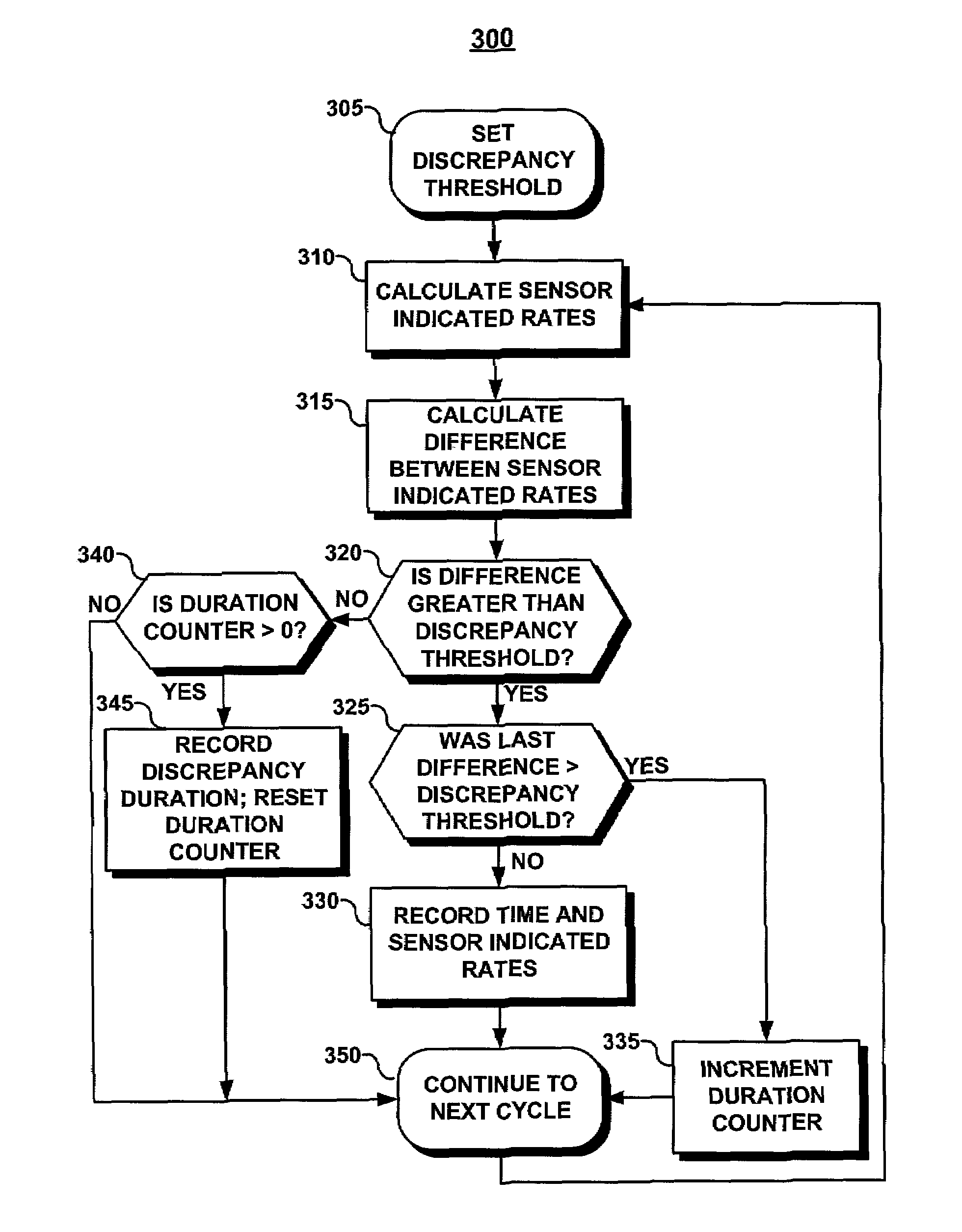
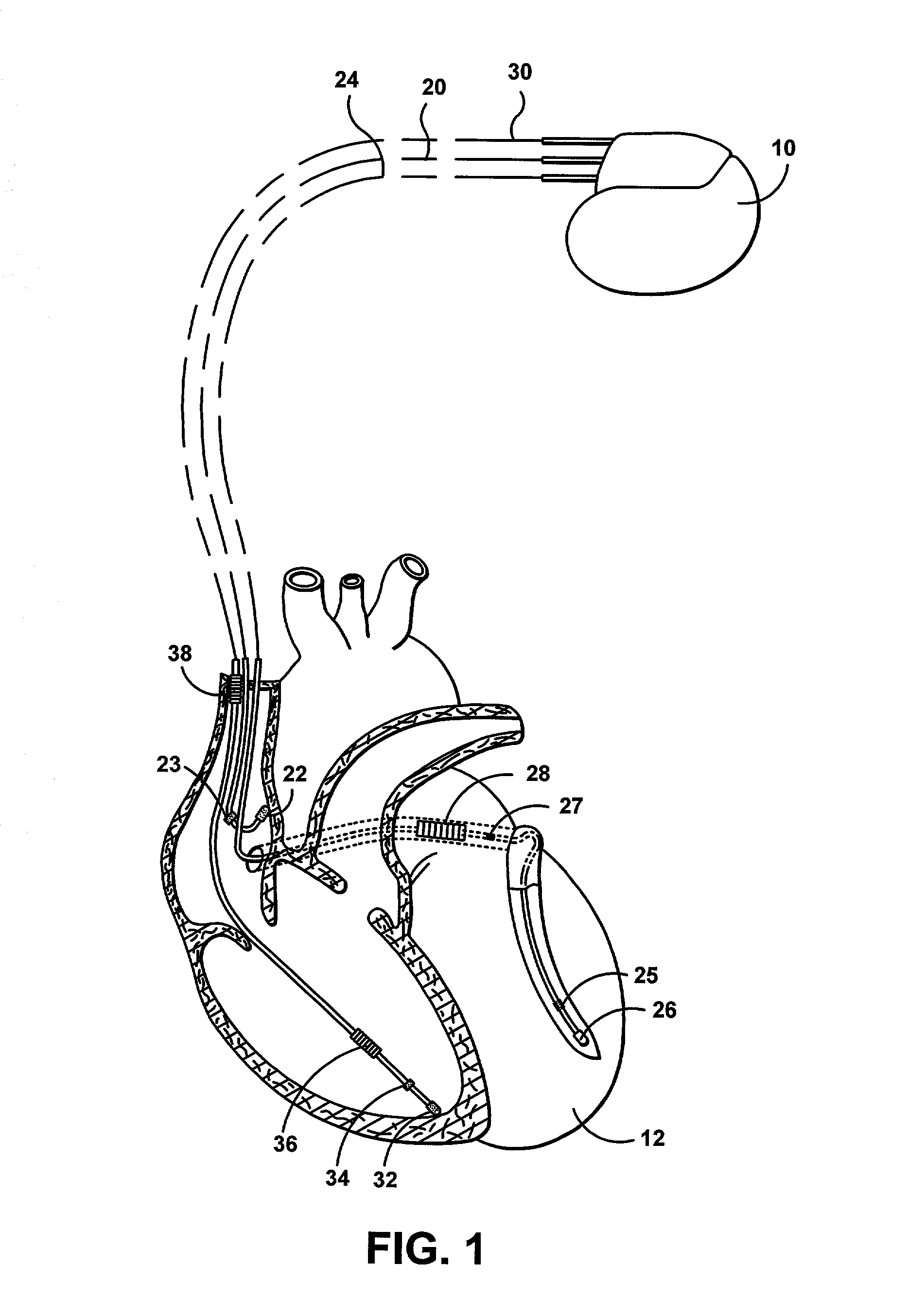
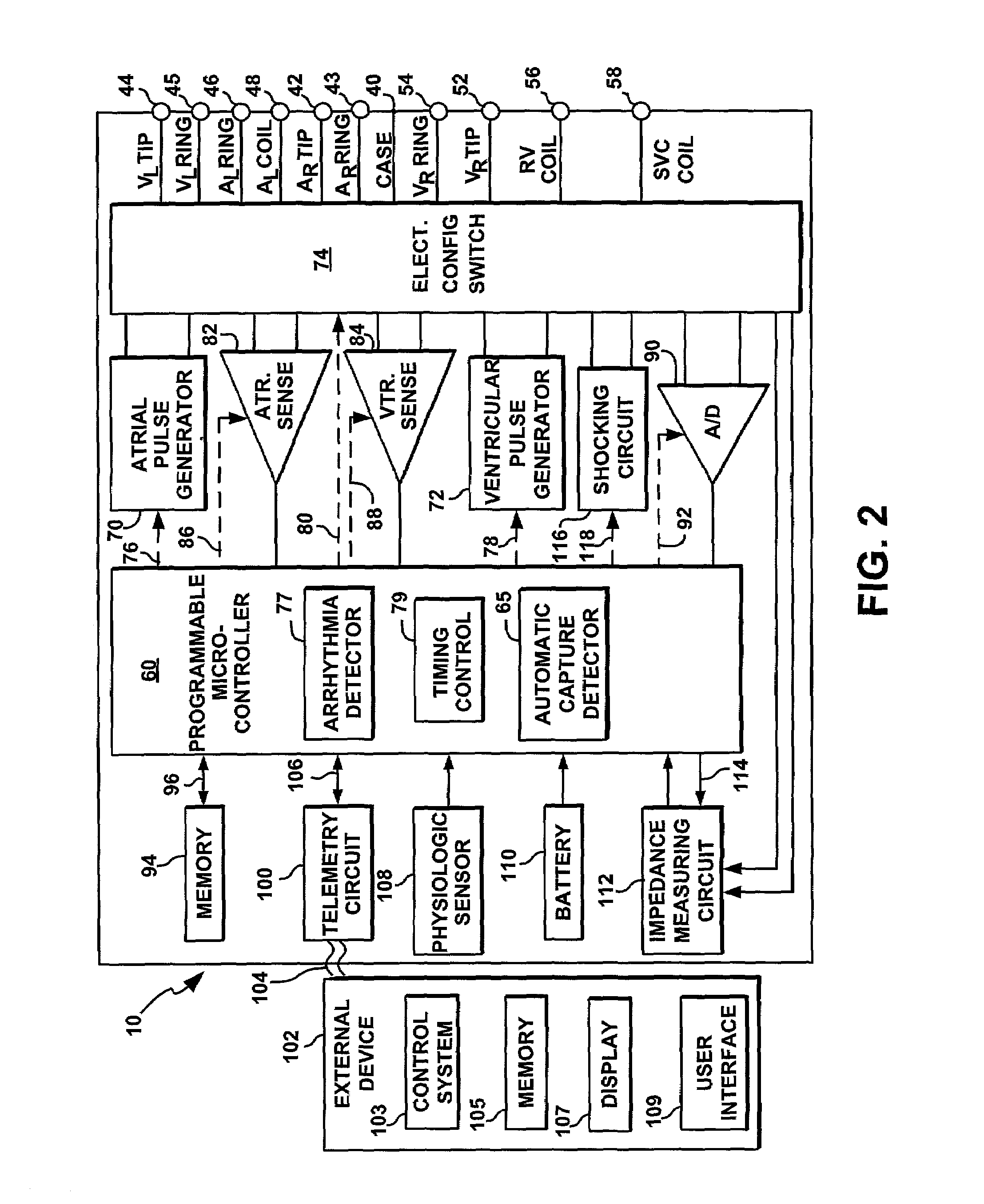
[0045]The present invention is directed at monitoring discrepancies between individual sensor indicated rates (or sensor levels) in a dual or multi-sensor rate responsive cardiac stimulation device. A cardiac stimulation device possessing rate responsive capabilities will thus be described in conjunction with FIGS. 1 and 2, in which the features of the present invention could be implemented. It is recognized, however, that numerous variations of such a device exist in which the methods of the present invention could be implemented without deviating from the scope of the present invention.

[0046...


PUM


Abstract

A cardiac stimulation device and method monitor and store discrepancies in sensor indicated rates determined from two or more sensors generating signals related to metabolic demand. One feature included in the present invention is a sensor cross-check record that stores the time, duration and sensor indicated rates whenever individual sensor indicated rates differ by more than a discrepancy threshold. This record allows a clinician to monitor an abnormal patient condition or determine if a sensor is not functioning properly or is programmed sub-optimally. Another feature provided by the present invention is a sensor cross-check histogram in which sensor indicated rate differences are stored. Histogram data aids the clinician in selecting programmable operating parameters that control the calculation of sensor indicated rates and the rate response of the cardiac stimulation device.

Description

FIELD OF THE INVENTION[0001]The present invention relates generally to an implantable cardiac stimulation device capable of providing rate-responsive stimulation according to multiple sensor signals and, in particular, to a method for monitoring discrepancies that occur between individual sensor indicated rates.BACKGROUND OF THE INVENTION[0002]In the normal human heart, the sinus node, generally located near the junction of the superior vena cava and the right atrium, constitutes the primary natural pacemaker initiating rhythmic electrical excitation of the cardiac chambers. The cardiac impulse arising from the sinus node is transmitted to the two atrial chambers, causing a depolarization known as a P-wave and the resulting atrial chamber contractions. The excitation pulse is further transmitted to and through the ventricles, via the atrioventricular (A-V) node and a ventricular conduction system, causing a depolarization known as an R-wave and the resulting ventricular chamber cont...

Claims


Application Information

Patent Timeline
Patent Type & Authority Patents(United States)
IPC IPC(8): A61N1/18
CPCA61N1/36585A61N1/3702
Inventor PARK, EULJOON
Owner PACESETTER INC
Why Eureka
Try Eureka