Forage harvester blower

a blower and harvester technology, applied in the field of harvesters, can solve the problems of serious damage to the blower rotor and the blower housing, knife breakage, and blower damage, and achieve the effect of minimizing play, easy and accurate adjustment of the diameter, and optimal set up of the blower paddle distan

Inactive Publication Date: 2006-11-21
BLUE LEAF I P INC
View PDF10 Cites 7 Cited by
  • Summary
  • Abstract
  • Description
  • Claims
  • Application Information

AI Technical Summary

Benefits of technology

[0009]The present invention provides a solution to the above-mentioned problem of increased security hazards and considerable material loss of a harvester blower when a foreign object enters the blower by providing a blower capable of quickly and easily evacuating and removing a foreign object that has entered the blower. For that, the blower is provided with adjustment mechanism for at least locally adjusting the diameter (D) of the housing. By locally enlarging the diameter of the housing, e.g. when a foreign object gets stuck in the blower for instance between the rotor paddles and the housing, the present invention permits to reduce the risks of blow-up and expensive repair costs associated there with.
[0010]In addition, this solution has the additional effect of considerably improving blower efficiency. In conventional forage harvesters efficiency of the blowing unit decreases as the rotor blades or paddles wear out. When the rotor paddles wear out, the distance between the outer edges of the rotor paddles and the housing increases, which seriously reduces efficiency of the blower. It is required to frequently replace the worn out rotor paddles in order to maintain blower efficiency. However, this requires the blower unit to be dismantled and the rotor to be removed from the blower, which involves a substantial amount of work and which brings along serious additional costs. The present invention provides a solution therefore by providing a blower unit having a housing of which the diameter can be locally adjusted. According to the invention, the diameter of the housing can be adjusted such that the distance between the outer edges of the rotor paddles and the housing can be minimised. By doing so, the present invention thus provides a blower unit wherein blower efficiency is considerably improved.
[0012]The invention allows easy and accurate adjustment of the diameter of the housing by adjusting the position of a wear plate provided on the housing, either inwardly to the centre of the rotor or outwardly away from the centre of the rotor. For that purpose, in a preferred embodiment, the wear plate is pivotably hinged on the blower housing and movable such that the diameter (D) of the housing can be adjusted by pivoting the wear plate. In another embodiment, the wear plate is connected to the housing by mechanism of two adjustment assemblies, which are suitable for adjusting the position of said wear plate, whereby one assembly is provided on each side of said wear plate. More specifically, the wear plate is positioned in the blower in a way so it can pivot around its upper fixation (hinge) points, while the position of the wear plate can be adjusted by mechanism of the adjustment assemblies. The position of the wear plate can be adjusted in order to minimise the play between the outer edges of the rotor paddles and the inside of the blower housing. The invention ensures an optimal set up of the blower paddle distance to the wear plate and thereby ensures optimal blower efficiency. Furthermore, the distance of the housing to the outer edges of the rotor paddles can be easily adjusted in function of the wear and tear degree of the paddles. Replacement of worn out rotor paddles can be delayed and the rotor paddles can be used for a longer time.
[0013]In a further embodiment of the present invention each adjustment assembly comprises an active adjustment unit for manually adjusting the position of the wear plate and a passive adjustment unit for automatically adjusting the position of the wear plate. The active unit can be manually operated in order to manually position the wear plate on a certain desired distance from the rotor paddles. The passive adjustment unit can be automatically activated when the pressure F exerted on the wear plate exceeds a threshold value. The passive adjustment units can be automatically activated without intervention of an operator. More specifically, the passive adjustment unit comprises a security mechanism, which enables the wear plate to automatically retract outwardly when the pressure F exerted on the wear plate exceeds a certain threshold value. This may occur when a foreign object gets stuck in the blower, e.g. between the rotor paddles and the housing. The present invention thus permits to reduce the risks of blow-up and expensive repair costs associated there with. Automatic retraction of the wear plate facilitates the removal of foreign objects out of the blower unit and thus increases protection of the blower rotor from damage due to the action of these objects. The present invention thus provides a blower having improved security and facilitated handling. In a preferred embodiment, the active adjustment unit is provided on the housing and the passive adjustment unit is provided on the wear plate. In another preferred embodiment, the active adjustment unit is connected to the passive adjustment unit.
[0014]The present invention further provides the following advantages. The wear plate can be easily removed, creating easy access to the blower for an operator which needs to do maintenance work, e.g. replacing the blower paddles. Furthermore, the present invention enables to easily remove and replace the wear plate at minimal costs when it is worn.

Problems solved by technology

An important problem associated with conventional harvester blowers is that the blowers may be seriously damaged when a foreign object enters the blower.
Sometimes, during field activities foreign objects can enter the blower area and cause serious damage to the blower rotor and blower housing.
This causes the knife to break such that this piece gets stuck between a subsequent knife and counter knife.
In most cases, this results in a deformation of the shaft on which the blower rotor is mounted and / or in a deformation of the housing and a serious decrease in efficiency of the blower.
Presence of foreign objects in the blower may induce considerable material damage and material loss such that deformed rotor and / or housing will have to be removed and replaced, which involves expensive repair costs and which is time-consuming.
Furthermore, the blow-up phenomenon also involves serious risks from a security point of view, since the blower can break down during operation.

Method used


Image

  • Forage harvester blower
  • Forage harvester blower
  • Forage harvester blower

Examples


Embodiment Construction

[0021]The present invention will now be described with reference to certain embodiments and certain drawings but the invention is not limited thereto. The drawings are schematic. The terms “front”, “rear”, “forward”, “rearward”, “right” and “left” used throughout the specification are determined with respect to the normal direction of movement of the machine in operation and are not to be construed as limiting terms.

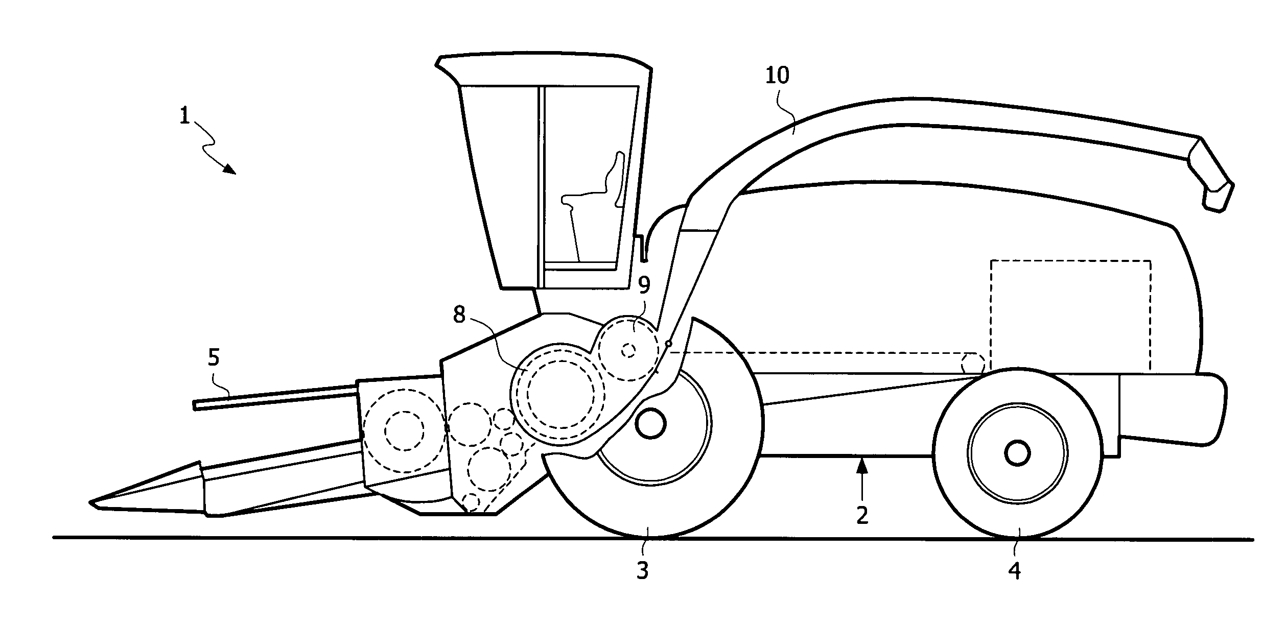
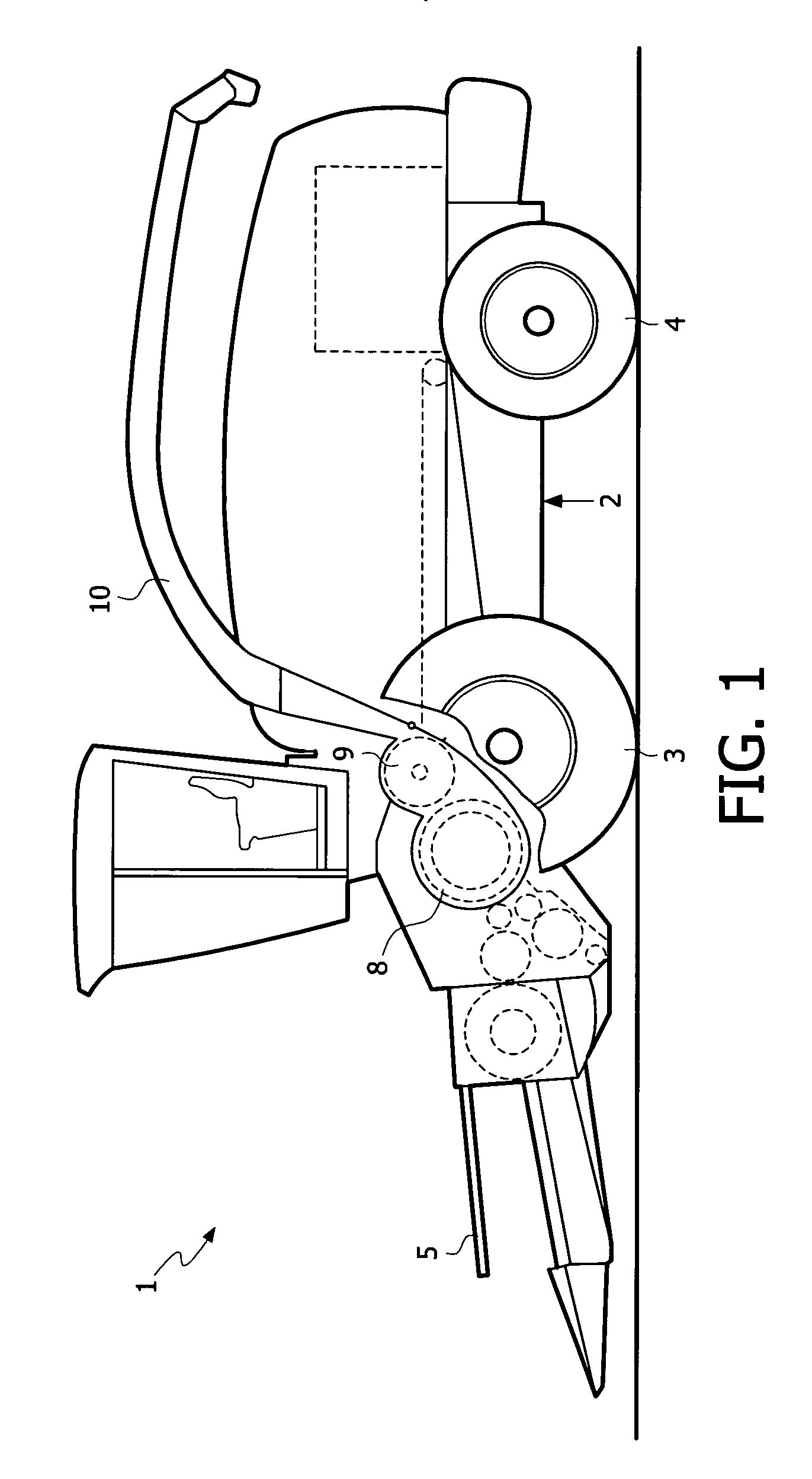
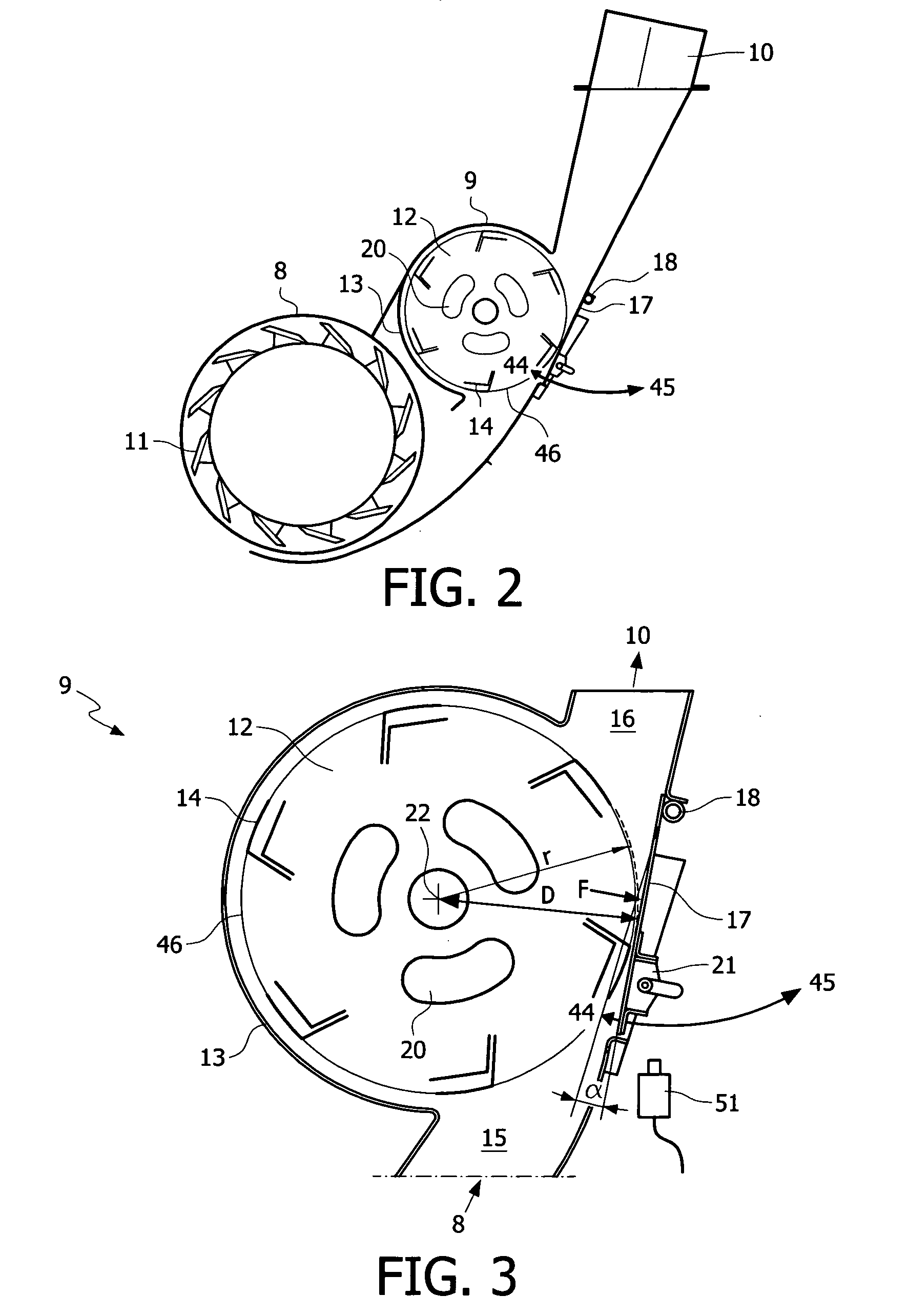
[0022]Referring to FIG. 1, there is shown a self-propelled forage harvester 1 which embodies the present invention. It being noted that the principles of the present invention could be applied to towed forage harvesters as well. The forage harvester 1 includes a main frame 2 supported on front and rear pairs of wheels 3 and 4, of which only one of each pair is shown. The forage harvester is shown equipped with a crop collecting apparatus, in the form of a row crop attachment 5, suitable for the harvesting of maize, but which can be replaced with a conventional windrow pi...


PUM


Abstract

The present invention relates to a forage harvester blower including a blower rotor having a plurality of generally radially extending rotor paddles which operate in a corresponding substantially cylindrical housing, characterised in that said housing is provided with adjustment mechanism for at least locally adjusting the diameter of the housing. The present invention further relates to a method for optimising the operation of a forage harvester blower and to a method for preventing damage to a forage harvester blower during operation.

Description

FIELD ON INVENTION[0001]The present invention relates to forage harvesters and more particularly relates to a forage harvester blower for receiving and delivering chopped forage. The present method also relates to an improved method for operating said forage harvester blower.BACKGROUND OF INVENTION[0002]Generally, forage harvesters chop crop material, such as grass or maize, into small particles for storage and subsequent feeding to livestock. Conventional harvesters comprise a rotating cutter head with a plurality of knives, which co-operates with a stationary shear bar to cut the crop material fed thereto into small particles and deliver it to discharge mechanism. It is well-known in forage harvesters to provide a blower for receiving chopped forage either directly from the cutter head or from kernel processing rolls or an impeller or other forage moving apparatus located between the cutter head and blower and for delivering the chopped forage to a forage collecting container such...

Claims


Application Information

Patent Timeline
Patent Type & Authority Patents(United States)
IPC IPC(8): A01D87/00A01D43/08A01D87/10
CPCA01D43/086A01D87/10
Inventor VAN VOOREN, SANDOR WILLYDEPESTEL, BERNARD ERIKTEETAERT, PIERRE
Owner BLUE LEAF I P INC
Why Eureka
Try Eureka