Gas chromatograph set

a gas chromatograph and set technology, applied in the field of gas chromatographs, can solve the problems of adverse effects on quantitative analysis, and line shift of chromatograms, so as to eliminate temperature differences, eliminate carrier gas flow rates, and reduce costs

Active Publication Date: 2006-11-21
SHIMADZU CORP
View PDF3 Cites 10 Cited by
  • Summary
  • Abstract
  • Description
  • Claims
  • Application Information

AI Technical Summary

Benefits of technology

[0016]In the present invention, since a plurality of carrier gas passages are formed inside the commonly-used metal plate, it is possible to eliminate a temperature difference among the carrier gas passages, and consequently to eliminate a difference in the carrier gas flow rates among the gas chromatographs.
[0017]Since the flow passage assembly is shared, it becomes possible to cut costs.
[0019]Moreover, with respect to the usage method of a gas chromatograph to which the present invention is suitably applied, a system in which two sets of gas chromatographs are installed to make a pair, with a sample is injected into one of the gas chromatographs so that a difference of detection signals between the two detectors can be obtained, is proposed. With this system, since a difference between detection signals from the detectors of the two gas chromatographs is obtained, it becomes possible to obtain a stable base line, and consequently to carry out an accurate quantitative analysis.

Problems solved by technology

In the case of using a packed column in which a filler has been filled up as the column, since a bleeding component from the packed column is large, upon a temperature-rise analysis (that is, a method in which the temperature of the packed column raises during analysis), a base line on the chromatogram fluctuates largely, affecting adversely on a quantitative analysis.
It has generally been known that, even if the volume flow rate of gas is constant, there is a change of 0.6% in the mass flow rate when the surrounding temperature changes by 1° C. Moreover, the temperature coefficient of the flow-rate sensor is about 0.4% / ° C. For this reason, a difference in a level of 2 to 3% occurs between the carrier-gas flow rates of the two carrier gas passages due to the above-mentioned temperature difference of 2 to 3° C. Consequently, base-line fluctuations occur in the chromatogram, resulting in adverse effect on the quantitative analysis.
There are differences among the flow rates of carrier gases, supplied from carrier gas passages made of a plurality of flow-passage assemblies to supply gases to a plurality of packed columns due to the above-mentioned temperature difference in the passage assemblies, resulting in a base-line shift of chromatogram that affects adversely on the quantitative analysis.

Method used


Image

  • Gas chromatograph set
  • Gas chromatograph set
  • Gas chromatograph set

Examples


Embodiment Construction

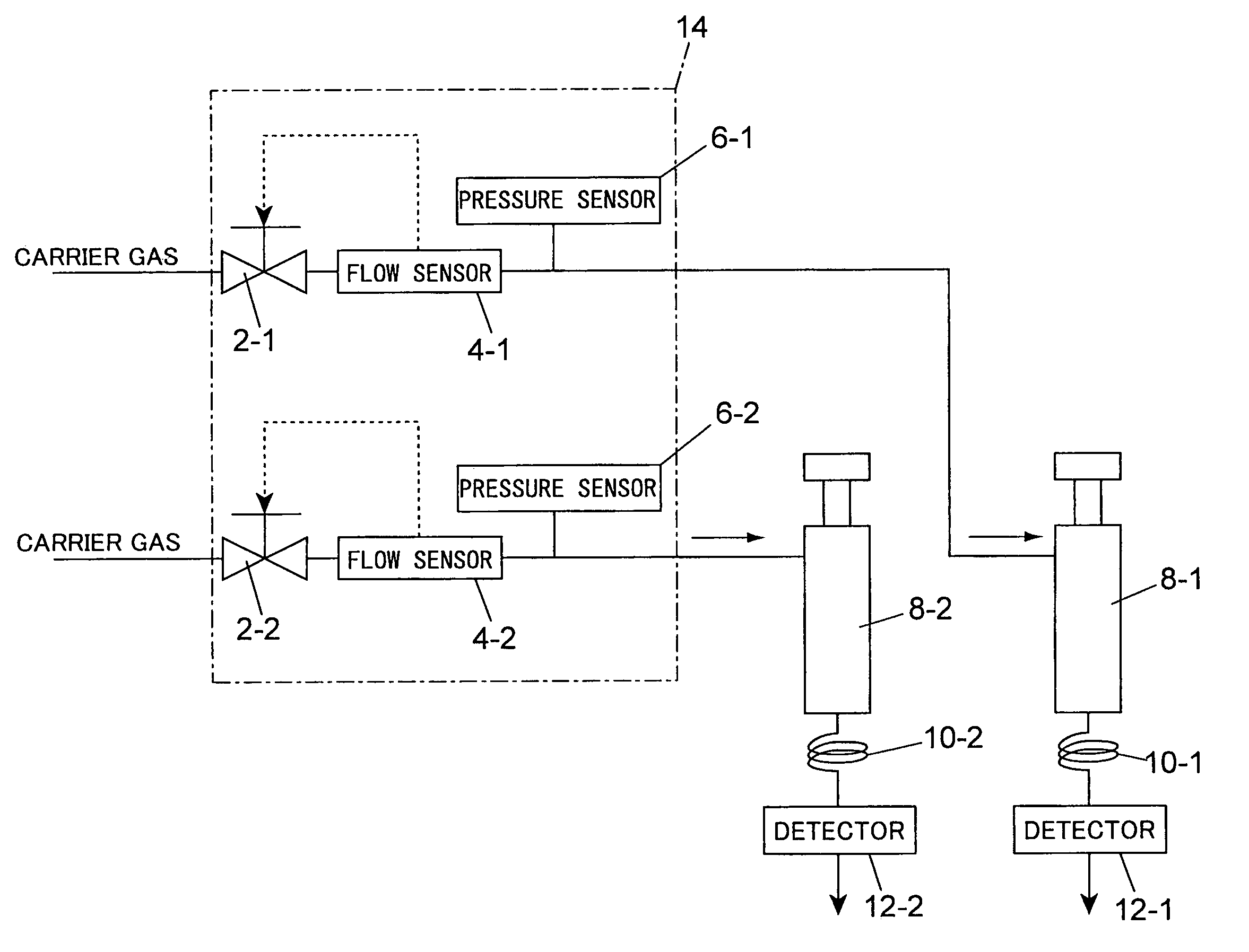
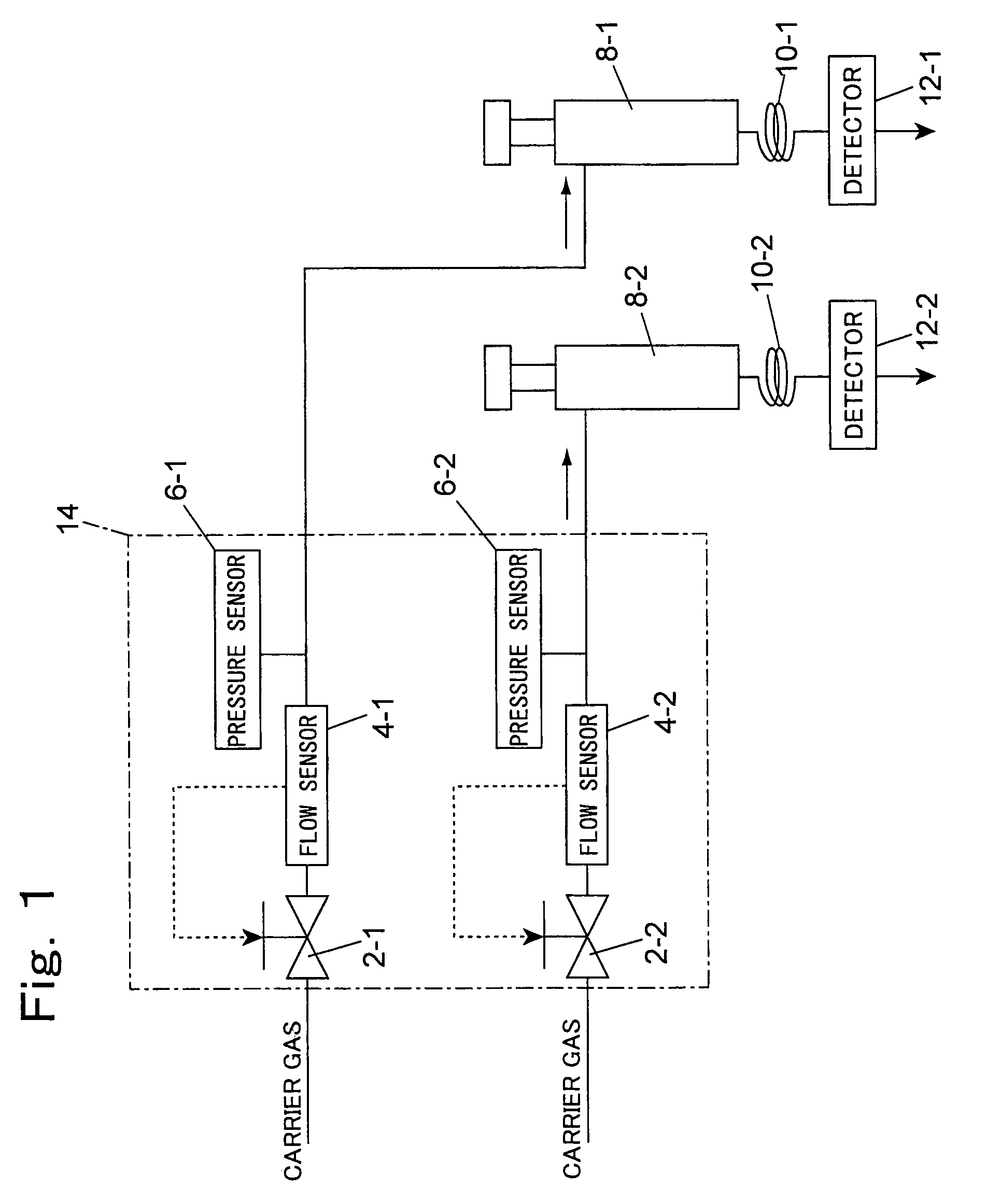
[0025]FIG. 1 schematically shows one embodiment. Two sets of gas chromatographs are provided. In one of the gas chromatographs, a carrier gas supply unit, which supplies a carrier gas to a column 10-1 through an injection port 8-1, is provided with a valve 2-1 that is connected to a carrier gas inlet, a flow-rate sensor 4-1 placed on the downstream side of the valve 2-1 and a pressure sensor 6-1. The valve 2-1 is feed-back controlled based upon a detection signal from the flow-rate sensor 4-1 so as to fix the flow rate to a predetermined value.

[0026]The other gas chromatograph also has the same structure, and a carrier gas supply unit, which supplies a carrier gas to a column 10-2 through an injection port 8-2, is provided with a valve 2-2 that is connected to a carrier gas inlet, a flow-rate sensor 4-2 placed on the downstream side of the valve 2-2 and a pressure sensor 6-2. The valve 2-2 is also feed-back controlled based upon a detection signal from the flow-rate sensor 4-2 so as...


PUM

PropertyMeasurementUnit
temperatureaaaaaaaaaa

Abstract

A gas chromatograph set of the present invention comprises a plurality of gas chromatographs and a flow passage assembly. Each of the gas chromatographs includes a column for separating sample-components, a carrier gas supply unit for supplying a carrier gas to the column and a detector for detecting eluted components from the column. The carrier gas supply unit comprises a carrier gas passage, and a flow controller unit for controlling a flow-rate that is connected to the carrier gas passage. The flow passage assembly comprises a metal plate inside which the carrier gas passages of the gas chromatographs are formed.

Description

BACKGROUND OF THE INVENTION[0001]1. Field of the Invention[0002]The present invention relates to a gas chromatograph used for measuring component concentrations in various samples.[0003]2. Description of the Related Art[0004]A gas chromatograph is provided with a column for separating sample components, a carrier gas supply unit for supplying carrier gas to the column and a detector for detecting eluted components from the column, and also has an injector for injecting a sample into the carrier gas, which is placed on the upstream side of the column.[0005]A flow controller unit for controlling a flow rate, which includes a valve and a flow-rate sensor, is installed in the carrier gas supply unit so that a carrier gas, supplied from a carrier gas inlet, is supplied to a column from the valve through the flow-rate sensor.[0006]With respect to the carrier gas supply unit, a structure in which a carrier gas passage is formed inside a metal substrate has been proposed (see Japanese Paten...

Claims


Application Information

Patent Timeline
Patent Type & Authority Patents(United States)
IPC IPC(8): G01N30/04G01N30/02G01N30/20G01N30/32G01N30/26G01N30/46G01N30/60G01N30/62G01N30/78
CPCG01N30/20G01N30/466G01N2030/025G01N30/88
Inventor FURUKAWA, MASANAO
Owner SHIMADZU CORP
Why Eureka
Try Eureka