Spinal fusion implant

a technology of spinal fusion and implant, which is applied in the field of spinal fusion implants, can solve the problems of disc or vertebral body displacement, chronic back pain, and disc or vertebral body damage,

Active Publication Date: 2006-11-21
GLOBUS MEDICAL INC
View PDF16 Cites 249 Cited by
  • Summary
  • Abstract
  • Description
  • Claims
  • Application Information

AI Technical Summary

Problems solved by technology

The spinal disc and / or vertebral bodies may be displaced or damaged due to trauma, disease, degenerative defects, or wear over an extended period of time.
One result of this displacement or damage to a spinal disc or vertebral body may be chronic back pain.
The mass of a herniated or “slipped” nucleus tissue can compress a spinal nerve, resulting in leg pain, loss of muscle control, or even paralysis.
As these overlapping laminated plies of the anulus begin to buckle and separate, either circumferential or radial anular tears may occur, which may contribute to persistent or disabling back pain.
Adjacent, ancillary spinal facet joints will also be forced into an overriding position, which may create additional back pain.
Whenever the nucleus tissue is herniated or removed by surgery, the disc space will narrow and may lose much of its normal stability.
While this treatment may help alleviate the pain once the vertebrae have been successfully fused together, there remains the possibility that the surgical procedure may not successfully or fully bring about the intended fusion.
While it is generally known that providing a through-hole from the top to bottom surfaces helps promote bone growth in the treated area, the structure of the front, back, and side walls often substantially obscure or do not permit confirmation that fusion is taking place as desired.
This difficulty of subsequently confirming that fusion is adequately taking place is particularly problematic when the spacer is made of radio opaque materials.
Thus, while the use of radio opaque materials can be beneficial for providing greater structural rigidity of the spacer and for helping the physician to identify the position of the implant during insertion, these materials can have the disadvantage of limiting the ability to later confirm the implant has served its intended purpose of fusing the treated area.
Another disadvantage that results from prior art spacer designs is that of solid sidewalls or sidewalls with limited openings limits fusion of the treated area principally to the opening on the upper and lower sides of the spacer, if one is provided.
Thus, while a spacer having an essentially closed or solid structure may maintain rigidity of the spacer, it does not provide optimal conditions for fusion to take place.
Spinal fusion procedures can present several challenges because of the small clearances around the spacer when it is being inserted into position.
For this reason, distraction of the treated area typically is greater than the implant itself.
Such increases in height or width of the profile of the spacer when coupled or in communication with instrumentation means that additional space is needed in order to insert the spacer.
In some circumstances, providing for this additional clearance space can be difficult to achieve.

Method used


Image

  • Spinal fusion implant
  • Spinal fusion implant
  • Spinal fusion implant

Examples


Embodiment Construction

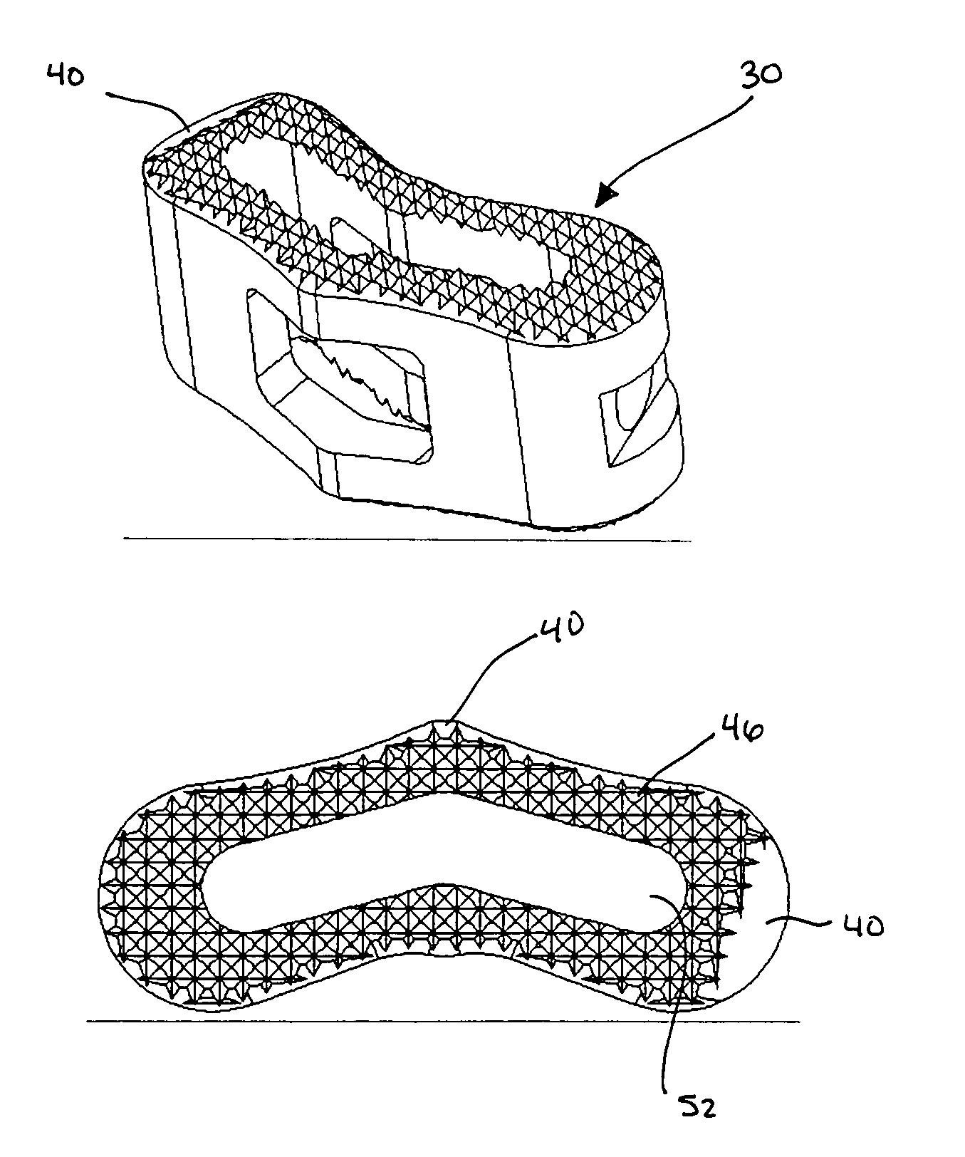
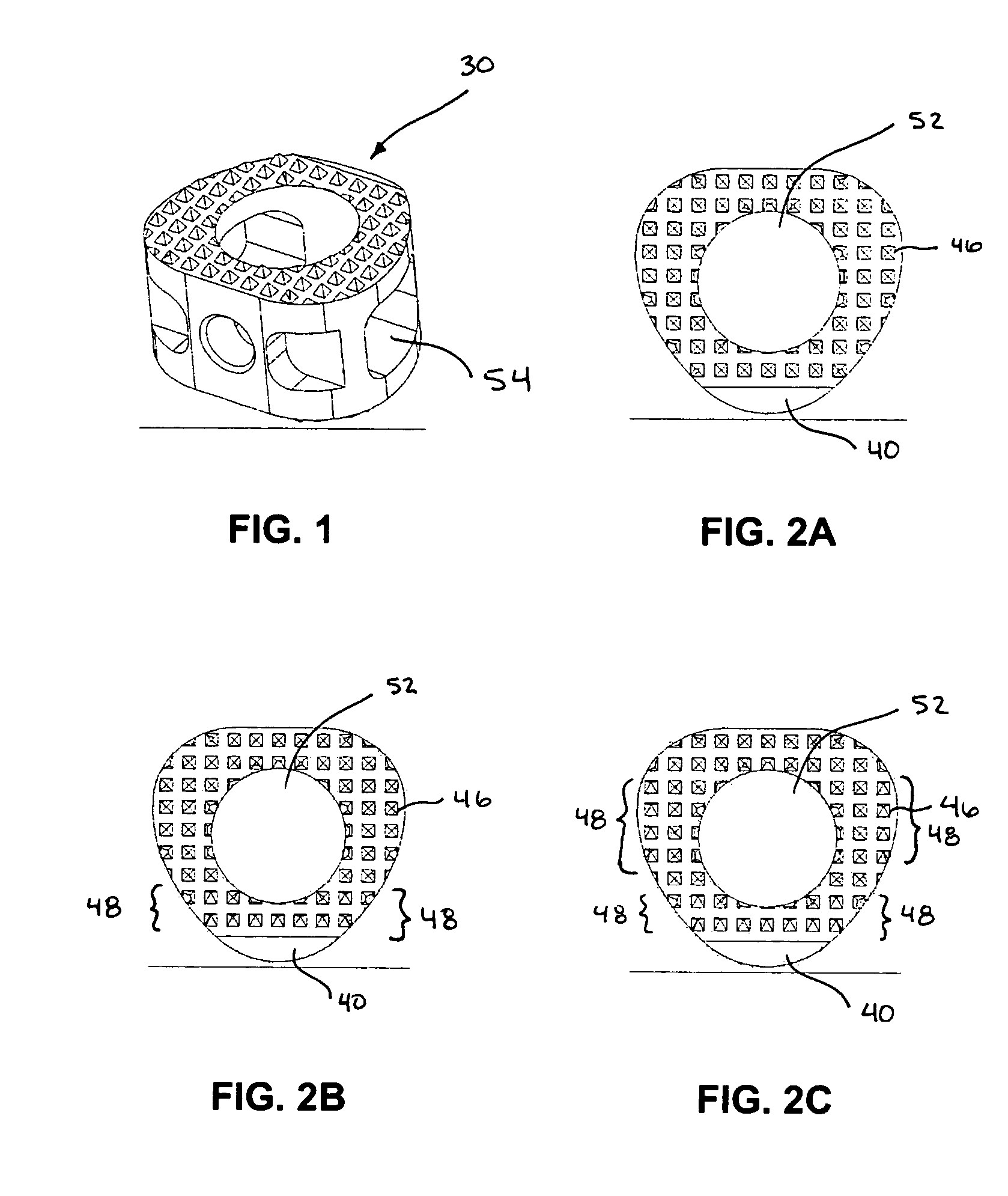
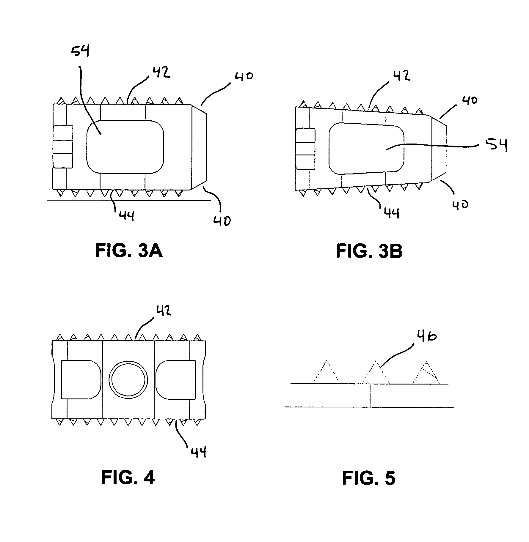
[0035]The present invention relates generally to implantable spacers 30 that can be used to fuse together a treated area of the spine while restoring or maintaining the proper spacing and natural curvature of the spine. The treated area may include regions between adjacent vertebral bodies so that the height of the spacer corresponds approximately to the height of the disc. More preferably, however, the height of the spacer of the present invention is greater than the height of a disc alone. For instance, the treated area of the spine may be prepared by the physician by removing all or part of at least one vertebral body.

[0036]As explained in greater detail below, several features of the invention allow for more efficient insertion or placement of the spacers into a desired position. Additionally, the present invention also provides suitable rigidity and integrity for supporting the spine during fusion while also providing greater ability to confirm that fusion is taking place as de...


PUM

PropertyMeasurementUnit
contact areaaaaaaaaaaa

Abstract

The present invention relates to spacers that are configured to promote fusion. Windows or openings in the sidewalls of the fusion spacers may be provided to allow a physician to view the treated area to confirm that fusion has occurred or to check on the progress of treatment. Fusion spacers of the invention may have two or more pairs of openings or windows that allow viewing of the treated area from different perspectives.

Description

FIELD OF THE INVENTION[0001]The present invention relates to spacers for fusing vertebral bodies.BACKGROUND OF THE INVENTION[0002]The vertebrate spine is the axis of the skeleton on which all of the body parts “hang”. In humans, the normal spine has seven cervical, twelve thoracic and five lumbar segments. The lumbar spine sits upon the sacrum, which then attaches to the pelvis, and in turn is supported by the hip and leg bones. The bony vertebral bodies of the spine are separated by intervertebral discs, which act as joints but allow known degrees of flexion, extension, lateral bending, and axial rotation.[0003]The typical vertebra has a thick anterior bone mass called the vertebral body, with a neural (vertebral) arch that arises from the posterior surface of the vertebral body. The centra of adjacent vertebrae are supported by intervertebral discs. Each neural arch combines with the posterior surface of the vertebral body and encloses a vertebral foramen. The vertebral foramina o...

Claims


Application Information

Patent Timeline
Patent Type & Authority Patents(United States)
IPC IPC(8): A61F2/44A61F2/00A61F2/02A61F2/30A61F2/46
CPCA61F2/4455A61F2/4465A61F2/4611A61F2002/30062A61F2002/3008A61F2002/30774A61F2002/30777A61F2002/4475A61F2210/0004A61F2250/0098A61F2310/00023A61F2002/30593
Inventor PAUL, DAVID C.
Owner GLOBUS MEDICAL INC
Why Eureka
Try Eureka