Method of operating a fuel cell power plant

a fuel cell and power plant technology, applied in the direction of fuel cells, electrochemical generators, chemical instruments and processes, etc., can solve the problems of affecting the operation of the fuel cell, the failure of the fuel cell to meet the needs of the user, and the degradation of the fuel cell operation by carbon monoxide, so as to reduce the complexity and reliability of the components, maintain the overall water balance, and reduce the energy requirement

Inactive Publication Date: 2006-11-21
GM GLOBAL TECH OPERATIONS LLC
View PDF6 Cites 17 Cited by
  • Summary
  • Abstract
  • Description
  • Claims
  • Application Information

AI Technical Summary

Benefits of technology

[0026]It has been found that such water transfer devices afford significant advantages over water management systems known in the art. In particular, such systems afford advantages maintaining an overall water balance in the system under a range of operating conditions, reduced energy requirements, reduced component complexity and reliability, and enhanced operating safety.

Problems solved by technology

Such MEAs are, accordingly, relatively expensive to manufacture and require controlled operating conditions in order to prevent degradation of the membrane and catalysts.
Unfortunately, carbon monoxide will degrade the operation of the fuel cell, particularly PEM fuel cells.
The use of heat exchangers presents issues, however.
Moreover, the liquid condensate produced by the heat exchangers must be vaporized for re-use in the system, creating an additional energy load and inefficiencies in the system.
However, water management systems among those known in the art do not adequately address these needs, due to problems such as their inability to maintain true water balance over a wide range of operating conditions, mechanical complexity and reliability, increased system energy requirements, and potential safety issues.

Method used


Image

  • Method of operating a fuel cell power plant
  • Method of operating a fuel cell power plant
  • Method of operating a fuel cell power plant

Examples


Embodiment Construction

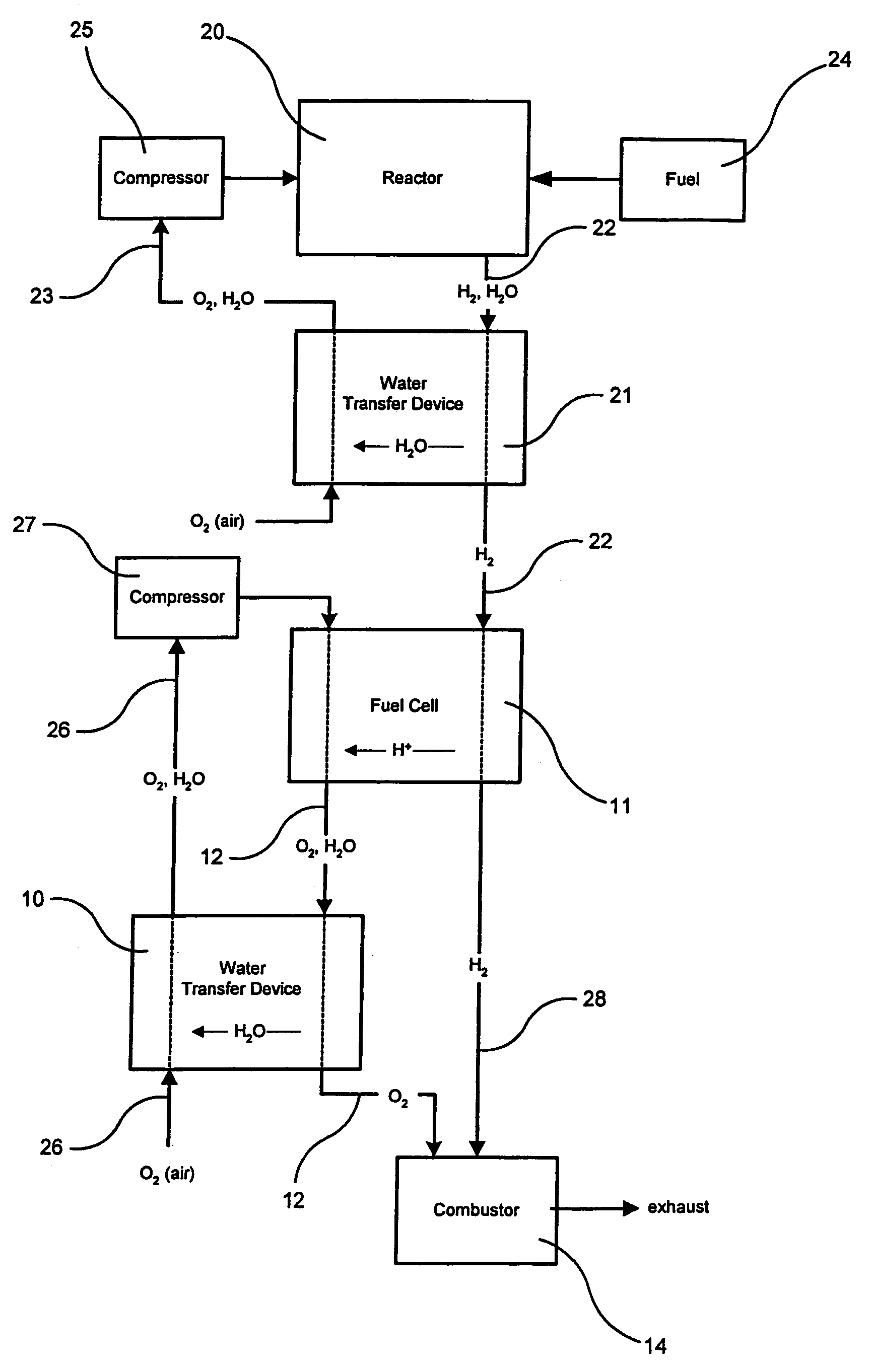
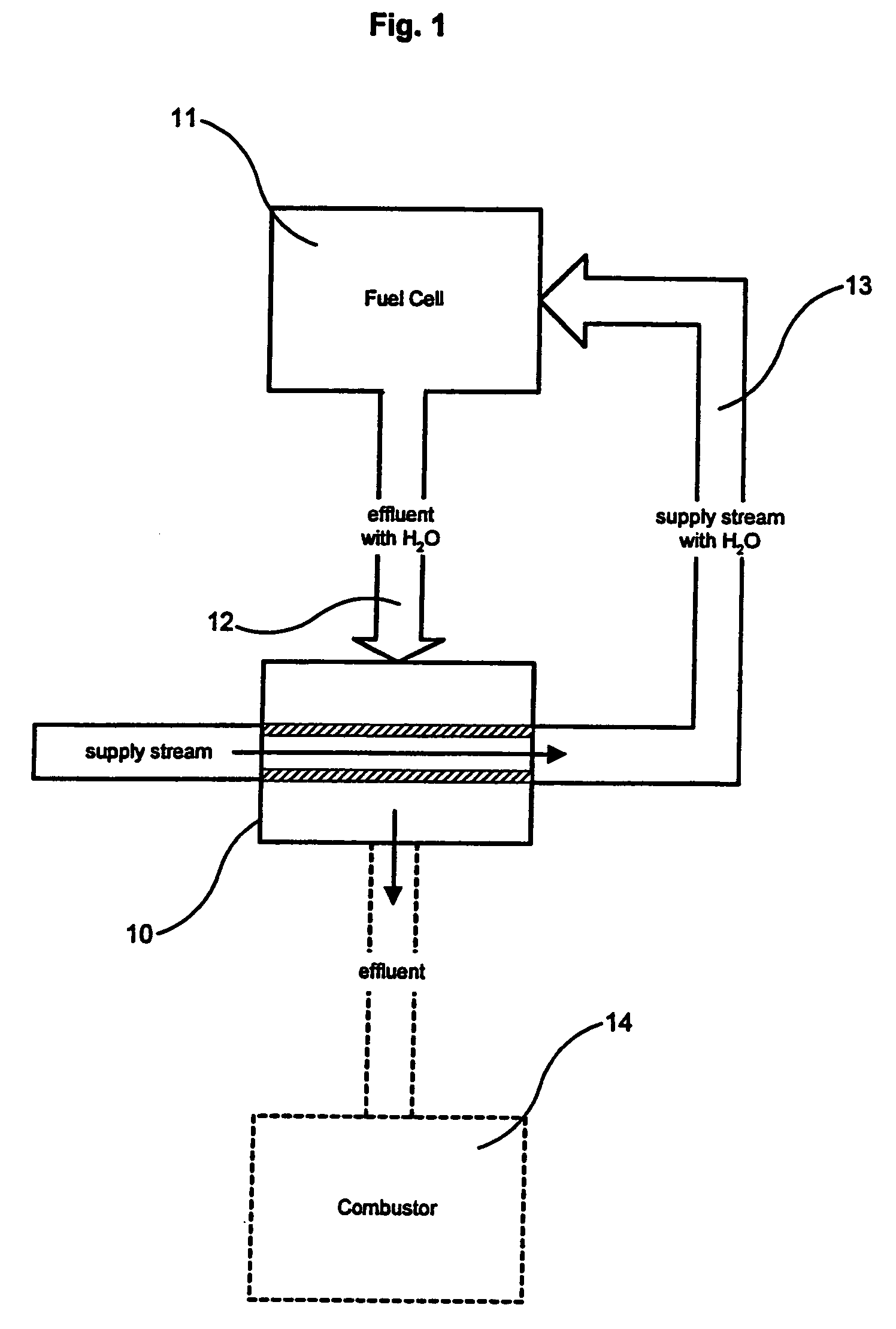
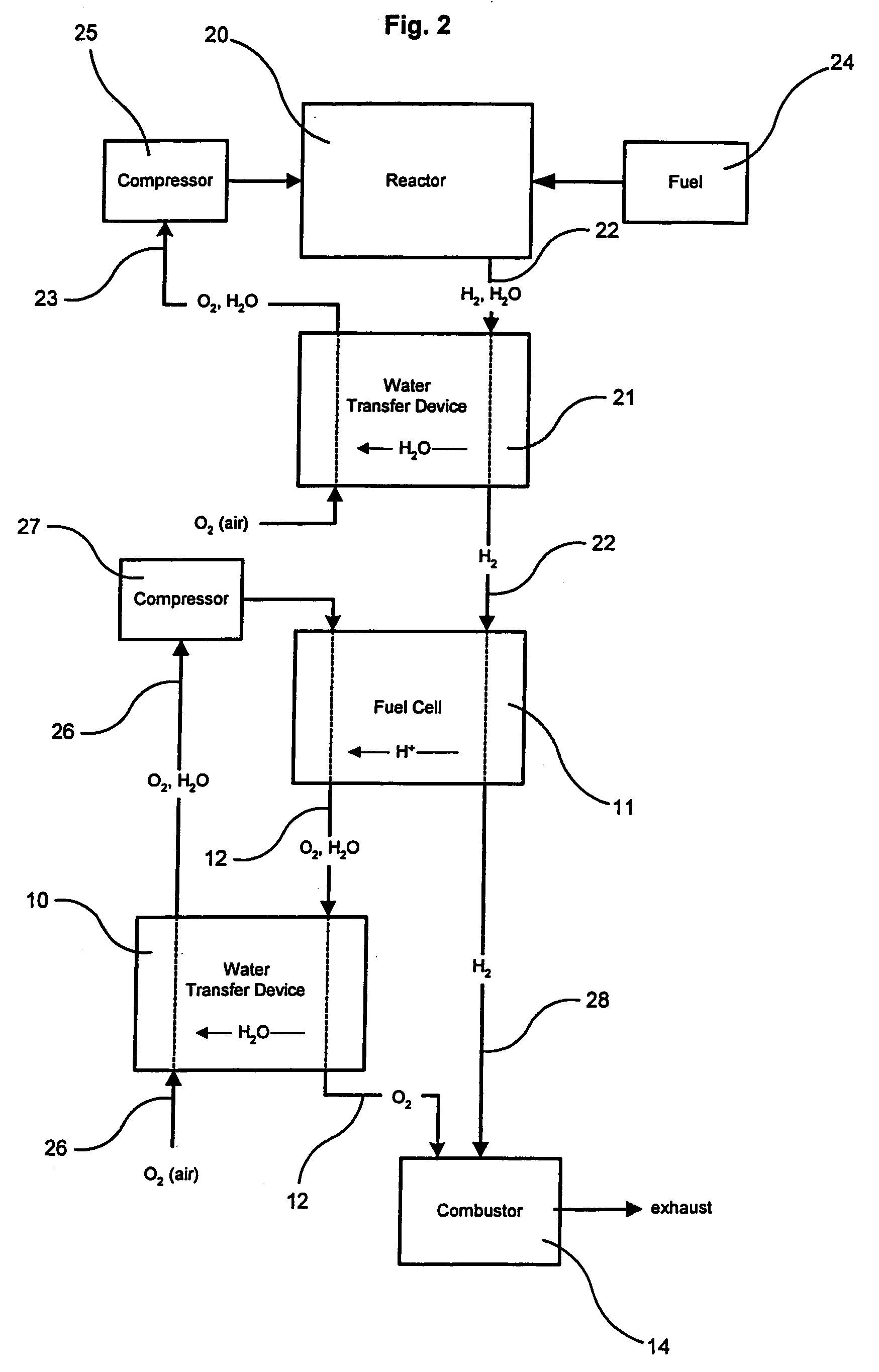
[0032]The present invention provides a fuel cell system. As referred to herein, a “fuel cell system” is an apparatus comprising a fuel cell and a water transfer device. The water vapor transfer device transfers water vapor from an effluent of the fuel cell to another component of the fuel cell system. In a particular embodiment, as depicted in FIG. 1, the water transfer device (10) transfers water vapor from a fuel cell (11) effluent stream (12) that contains oxygen and water, to an input stream (13) of the fuel cell. Preferably, the water vapor is transferred from the cathode effluent of the fuel cell. A preferred embodiment of a fuel cell system also comprises a combustor (14), for burning anode fuel cell effluent. Also preferably, the fuel cell system is a hydrocarbon fuel cell plant, embodiments of which are depicted in FIGS. 2, 3 and 4.

[0033]As referred to herein, a “fuel cell” may be a single cell for the electrochemical creation of electricity, preferably a PEM fuel cell, usi...


PUM

PropertyMeasurementUnit
temperatureaaaaaaaaaa

Abstract

A fuel cell system extracts water from the effluent of a fuel cell for supply to other components of the fuel cell system that require water. A preferred embodiment is a fuel cell system, for the production of electricity from hydrogen gas and an oxidant, comprising:(a) a fuel cell comprising an anode input for a hydrogen-containing anode supply stream, a cathode input for an oxidant-containing cathode supply stream, and a cathode output for cathode effluent comprising water produced by said fuel cell; and(b) a water transfer device, connected to said fuel cell, that transfers water from said cathode effluent to said anode supply stream.

Description

CROSS-REFERENCE TO RELATED APPLICATIONS[0001]This application is a divisional of U.S. patent application Ser. No. 10 / 627,145 filed on Jul. 25, 2003, now abandoned, which is a continuation of U.S. patent application Ser. No. 09 / 910,331 filed on Jul. 20, 2001, now U.S. Pat. No. 6,630,260. The disclosure of the above application is incorporated herein by reference.BACKGROUND OF THE INVENTION[0002]This invention relates to fuel cell power plants for the production of electricity from the electrochemical reaction of hydrogen and an oxidant. Preferred plants produce hydrogen from hydrocarbon fuel. In particular, this invention relates to fuel cell power plants having a device that transfers water vapor from the effluent of a fuel cell to components of the power plant that require water.[0003]Fuel cells are devices that convert electrochemical energy from the reaction of reducing and oxidizing chemicals, into electricity. Fuel cells have been used as a power source in many applications, an...

Claims


Application Information

Patent Timeline
Patent Type & Authority Patents(United States)
IPC IPC(8): H01M8/06H01M8/04H01M8/10C01B3/34C01B3/48
CPCC01B3/34C01B3/48H01M8/04119H01M8/0612C01B2203/00C01B2203/0244C01B2203/0283C01B2203/0405C01B2203/044C01B2203/047C01B2203/0495C01B2203/066C01B2203/0838C01B2203/0844C01B2203/0866C01B2203/142C01B2203/146C01B2203/148C01B2203/82Y02E60/50
Inventor FORTE, JAMESON RBURCH, STEVENBRUNDAGE, MARK A
Owner GM GLOBAL TECH OPERATIONS LLC
Why Eureka
Try Eureka