Carbon fiber reinforced base material, preform and composite material comprising the same

a technology of carbon fiber reinforced base material and preform, which is applied in the direction of synthetic resin layered products, textiles and paper, printing, etc., can solve the problems of composite using preform, too stiff to be drapable, and high cos

Inactive Publication Date: 2006-11-21
TORAY IND INC
View PDF22 Cites 39 Cited by
  • Summary
  • Abstract
  • Description
  • Claims
  • Application Information

AI Technical Summary

Benefits of technology

[0018]The carbon fiber reinforced substrate of the invention comprises a fabric composed of carbon fiber bundles and a first resin adhering to the fabric, and is characterized in that the carbon fiber bundles each of which comprises numerous continuous carbon filaments, that the tensile modulus of the carbon fiber bundles is 210 GPa or more, that the fracture strain energy of the carbon fiber bundles is 40 MJ / m3 or more, and that the amount of the first resin adhering to the fabric is in a range from 1 to 20 parts by weight per 100 parts by weight of the fabric.

Problems solved by technology

However, it also has a disadvantage that it is too stiff to be drapable.
Furthermore, the production of a composite using the prepreg has such problems as high cost and low productivity.
However, though the injection or infusion molding is excellent in composite productivity, the substrate used (for example, a dry woven fabric) has problems in view of handling properties such that texture slippage is liable to occur (un-stability of form), that the substrate is so less stiff as to allow easy bending, and that layers of the substrate do not adhere to each other when laminated (no tacky property).
In addition, since the matrix resin must be low in viscosity, the composite has a problem of being low in mechanical properties, compared with the composite formed with a matrix resin having a high viscosity as used in the above-mentioned prepreg.
These problems present a problem that the composite obtained cannot sufficiently exhibit the properties peculiar to carbon fibers and does not have the mechanical properties expected from the properties of the carbon fibers used.
However, the proposal cannot improve, or can improve only insufficiently, mechanical properties, though it can improve the handling properties of the substrate.
That is, for example, the very high levels of mechanical properties required for primary or principal structure elements of aircraft cannot be achieved even if a woven fabric or the like is merely coated with a resin, and in the case where the carbon fibers used themselves do not have the necessary properties, the composite obtained using them cannot exhibit necessary mechanical properties (especially the compression strength after impact) either.
Moreover, in the injection or infusion molding methods described in the above-mentioned proposals, since a sheet composed of carbon fiber bundles merely arranged in one direction cannot be handled with the fiber orientation kept as it is in a dry state, a bi-directional woven fabric is used.
That is, even though the required properties of the carbon fibers to be used and the form of the fabric composed of the carbon fibers are especially important factors for exhibiting high mechanical properties, the above-mentioned proposals do not disclose any explanation about such factors at all.

Method used


Image

  • Carbon fiber reinforced base material, preform and composite material comprising the same
  • Carbon fiber reinforced base material, preform and composite material comprising the same
  • Carbon fiber reinforced base material, preform and composite material comprising the same

Examples


example 1

[0208]The first resin A was freeze-crushed into particles. The average particle size D50 of the particles was 124 μm.

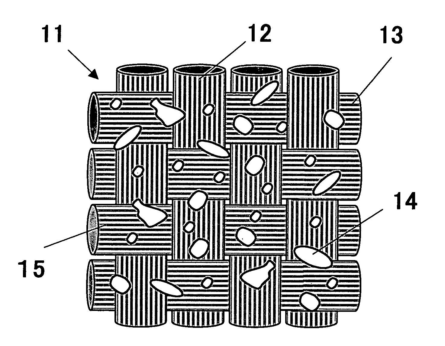
[0209]Using the carbon fiber bundles A as warp yarns and glass fiber bundles as auxiliary weft yarns, a uni-directional woven fabric A was formed. The woven fabric A was a plain weave, and had a thickness of 0.3 mm, a carbon fiber unit weight of 295 g / m2, 2.8 warp ends / cm and 3 weft ends / cm. The obtained uni-directional woven fabric A was 3.5 mm in the width of each carbon fiber bundle used as a warp yarn and more than 10 in the ratio of the width to the thickness of the carbon fiber bundle, and was a flat woven fabric. Before weaving, each of the carbon fiber bundles A had a width of 5.8 mm and a thickness of 0.15 mm.

[0210]The particles of the first resin A were allowed to naturally drop to coat the obtained uni-directional woven fabric A through a vibration net for uniform dispersion, while they were weighed using an emboss roll and a doctor blade. In this coating, ...

example 2

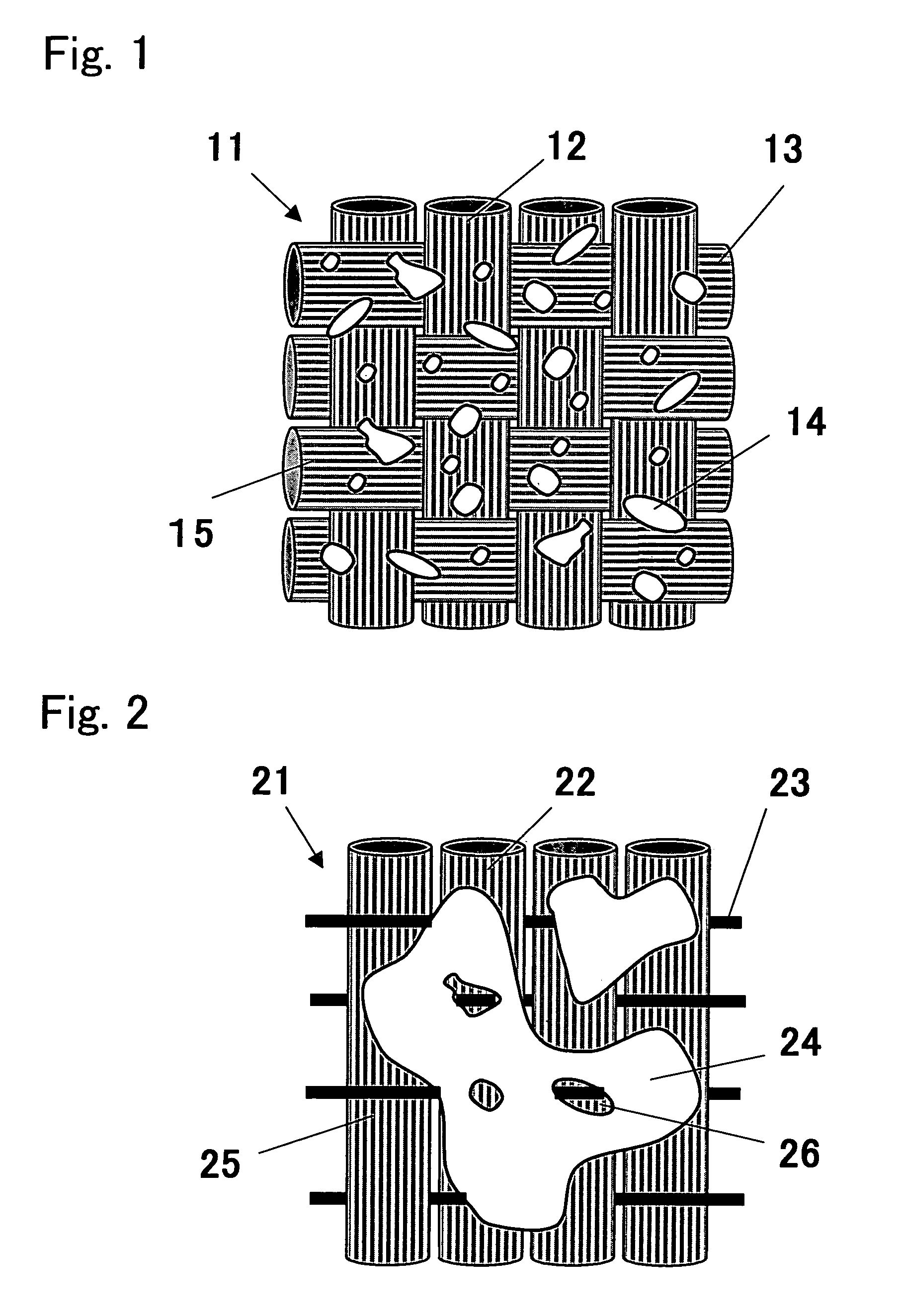
[0211]Fifty parts by weight of the first resin B and 50 parts by weight of the second resin were melt-kneaded at 170° C. using a kneader, and freeze-ground, to obtain particles consisting of both the resins integrated. The average particle diameter D50 of the particles was 38 μm. The second resin was not molten or did not flow at the flow initiation temperature of the first resin B, and both the resins were not compatible with each other.

[0212]The obtained particles were electrically charged using “Tricomatic (R)” II powder coating system produced by Nordson Corporation, while being uniformly dispersed by means of compressed air, to be applied to the uni-directional woven fabric A obtained as described in Example 1. In this coating, 100 parts by weight of the woven fabric were coated with 14 parts by weight of the particles. Furthermore, the coated fabric was heated in a range from 140 to 160° C., using a hot press roller, for letting the particles adhere to the uni-directional wove...

example 3

[0213]The carbon fiber bundles A were used as warp yarns, and glass fiber bundles were respectively covered with a nylon yarn with a low melting point (“Elder” produced by Toray Industries, Inc., 6 tex) for use as auxiliary weft yarns, to form a uni-directional woven fabric C. The woven fabric C was a plain weave, and had a thickness of 0.26 mm, a carbon fiber unit weight of 193 g / m2, 1.8 warp ends / cm and 3 weft ends / cm. The woven fabric C was 5.5 mm in the width of each carbon fiber bundle used as a warp yarn and more than 20 in the ratio of the width to the thickness of the carbon fiber bundle, and was a woven fabric flatter than the uni-directional woven fabric A of Example 1. A carbon fiber reinforced substrate C was obtained as described for Example 1, except that the woven fabric C was used and that 100 parts by weight of the woven fabric C were coated with 14 parts by weight of the first resin A. The obtained carbon fiber reinforced substrate C had a thickness of 0.37 mm, an ...


PUM

PropertyMeasurementUnit
thicknessaaaaaaaaaa
diametersaaaaaaaaaa
thicknessaaaaaaaaaa

Abstract

A carbon fiber reinforced substrate comprising a fabric composed of carbon fiber bundles and a first resin adhering to the fabric. Each of the carbon fiber bundles comprises numerous continuous carbon filaments, has the tensile modulus of 210 GPa or more, and has the fracture strain energy of 40 MJ/m3 or more. The amount of the first resin adhering to the fabric is in a range from 1 to 20 parts by weight per 100 parts by weight of said fabric. A preform comprising a laminate composed of plural layers of the carbon fiber reinforced substrate, wherein the layers are integrated by means of the first resin. A composite comprising the preform impregnated with a matrix resin.

Description

[0001]This application is a 371 of PCT / JP02 / 06696 filed Jul. 2, 2002.TECHNICAL FIELD[0002]The present invention relates to a carbon fiber reinforced substrate, a preform comprising the substrate, and a composite comprising the preform.[0003]The present invention relates to a carbon fiber reinforced substrate having excellent handling properties at forming a preform from the carbon fiber reinforced substrate. The handling properties mean at least any one property selected from the stiffness, form stability, drapability and tackiness in lamination, of the carbon fiber reinforced substrate.[0004]The invention also relates to a preform having excellent resin permeability at forming a composite from the carbon fiber reinforced substrate having such excellent handling properties.[0005]Furthermore, the invention relates to a composite having excellent mechanical properties, which is formed from the preform having excellent resin permeability. The mechanical properties mean at least one pro...

Claims


Application Information

Patent Timeline
Patent Type & Authority Patents(United States)
IPC IPC(8): B32B27/04B32B3/10C08J5/04B29B11/16B29B15/10B29C70/22B32B5/26D03D1/00D03D15/12D06M15/53D06M15/55D06M15/59D06M15/63D06M17/08
CPCB29B11/16B29B15/105B29C70/226B32B5/26B29L2031/3055Y10T428/24802B29L2031/3076D10B2101/12D10B2331/021B29L2031/3067Y10T442/2115Y10T442/2098Y10T442/2139Y10T442/2041Y10T442/2107Y10T442/2984Y10T442/2123Y10T442/2131B29C70/00B29C70/0035B32B27/42B32B5/024B32B9/007B32B27/38B32B27/34B32B2363/00B32B27/32B32B27/12B32B2377/00B32B2605/08B32B27/281B32B2605/18B32B2605/12B32B9/047B32B2262/106
Inventor WADAHARA, EISUKENISHIMURA, AKIRAHORIBE, IKUO
Owner TORAY IND INC
Why Eureka
Try Eureka