
Method and apparatus of magnetically transferring information signal from master medium to slave medium

a technology of information signal and master medium, which is applied in the direction of maintaining head carrier alignment, magnetic materials for record carriers, instruments, etc., can solve the problem of lowering the reliability of reproducing information, and achieve excellent magnetic transfer and accurate transfer

Inactive Publication Date: 2006-11-21
FUJIFILM HLDG CORP +1
View PDF5 Cites 0 Cited by
  • Summary
  • Abstract
  • Description
  • Claims
  • Application Information

AI Technical Summary

Benefits of technology

[0006]The present invention was made with the above-described problems in mind. The object of the present invention is to provide a method and an apparatus for magnetically transferring magnetic information signals held in a master medium to a slave medium in a state where the master medium and the slave medium are in close contact with each other, which is capable of executing accurate transfer of the magnetic patterns by defining the allowable range of the application direction of the transferring magnetic field.
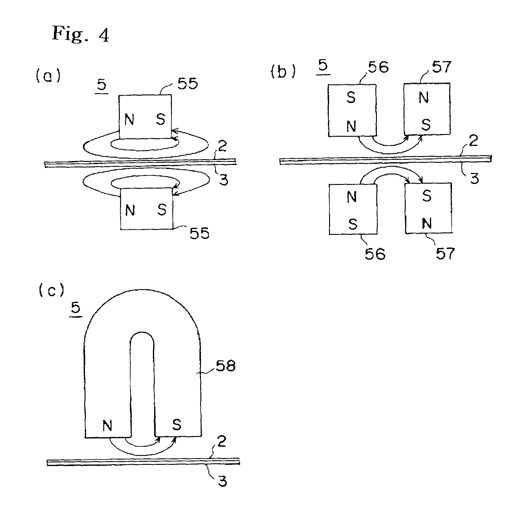
[0011]As the magnetic field generating means for applying the transferring magnetic field, an electromagnet device or a permanent magnet device can be used. However, the electromagnet device is preferably used because the conditions such as the magnetic field intensity and the like can be more easily set and regulated.
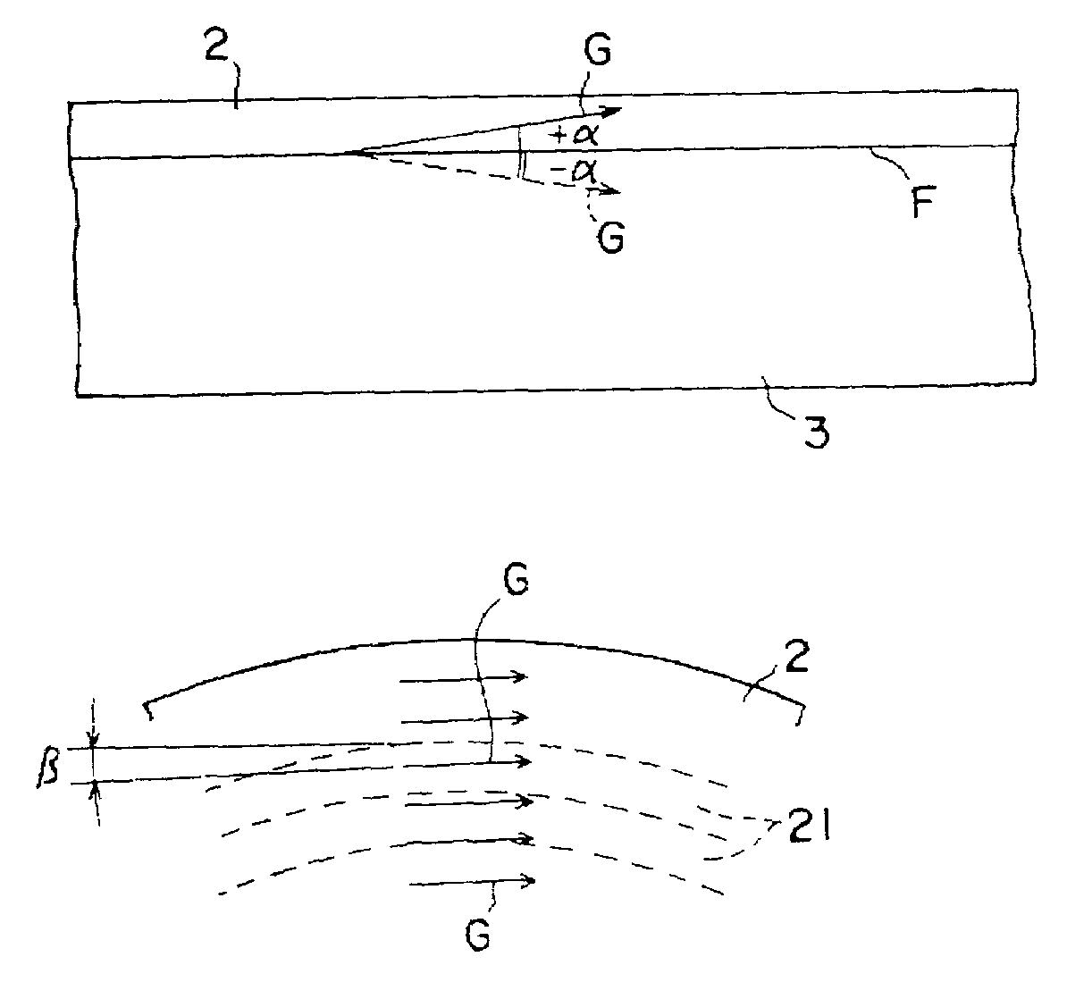
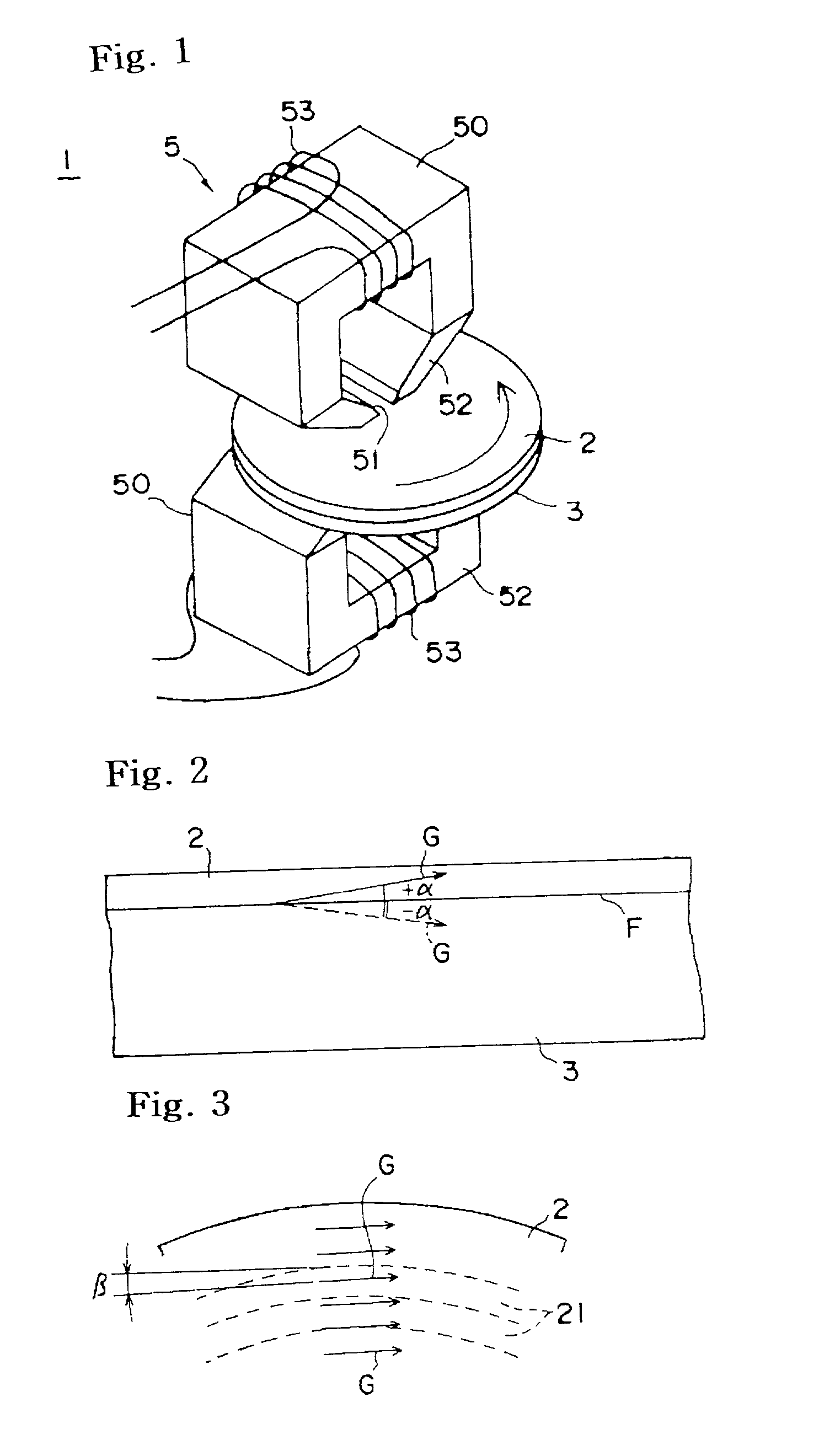
[0017]According to the aforementioned present invention, because when executing the magnetic transfer, the application angle of the transferring magnetic field is within a range of ±30° in a vertical direction with respect to the slave surface, or the application angle of the transferring magnetic field is within a range of ±30° with respect to the track direction on a plane parallel to the slave surface, or sum of absolute values of an application angle of the transferring magnetic field in a direction vertical to the slave surface and an application angle of the transferring magnetic field with respect to the track direction on a plane parallel to the slave surface is within 30°, an accurate transfer of the magnetic patterns can be executed with homogeneous properties on the whole surface of the slave medium and can assure an excellent tracking function in a case of servo signals to improve reliability thereof.
[0018]In constructing the magnetic transfer device, by regulating the application angle of the magnetic field for magnetic transfer within an allowable range as described above, an excellent magnetic transfer can be executed, so that design of accuracy in assembly of the whole device, intensity and distribution of the magnetic field in the magnetic field generating means and the like is easily performed.

Problems solved by technology

However, it is difficult that magnetic field generated by an actual magnetic field generating means is made to be parallel to a track direction and a slave surface in a plane direction and a vertical direction from an inner circumference portion to a whole outer circumference portion of the slave medium, and is made to be offset due to various factors.
Thus, when the transfer information is servo signals, a satisfactory tracking function cannot be obtained and reliability of reproducing the information is lowered.

Method used


Image

  • Method and apparatus of magnetically transferring information signal from master medium to slave medium
  • Method and apparatus of magnetically transferring information signal from master medium to slave medium
  • Method and apparatus of magnetically transferring information signal from master medium to slave medium

Examples


Embodiment Construction

[0025]Hereinbelow, description will be given for embodiments of the present invention in detail with reference to the accompanying drawings.

[0026]FIG. 1 is a perspective view showing main parts of a magnetic transfer apparatus for executing a magnetic transfer method according to an embodiment of the present invention. FIGS. 2 and 3 are views showing definitions of the application angle of transferring magnetic field, FIG. 4 is a schematic view showing another embodiment of a magnetic field generating means, and FIG. 5 is a schematic view showing principal steps of the magnetic transfer method according of the present invention. Note that each of the figures is a schematic view, and that dimension of each parts or the like shown therein is different from an actual dimension.

[0027]In the magnetic transfer apparatus of FIG. 1, during the magnetic transfer, a slave surface (magnetic recording surface) of a slave medium 2 (magnetic recording medium) is allowed to get in contact with an ...


PUM

PropertyMeasurementUnit
angleaaaaaaaaaa
coercive forceaaaaaaaaaa
coercive force Hcmaaaaaaaaaa

Abstract

When executing a magnetic transfer by bringing a master medium and a slave medium into close contact with each other and applying a transferring magnetic field, a permitted limit of the application direction of the transferring magnetic field is defined so that magnetic patterns can be accurately transferred. A slave medium 2 is previously initial DC magnetized in a track direction by applying a magnetic field to the slave medium in the track direction of a slave surface, and when executing a magnetic transfer by bringing the master medium 3 and the slave medium 2 into close contact with each other and applying the transferring magnetic field in the track direction of the slave surface, the application angle α of the transferring magnetic field is defined within a range of ±30° in a vertical direction with respect to the slave surface. Furthermore, the application angle of the transferring magnetic field is defined within a range of ±30° with respect to the track direction on a plane parallel to the slave surface.

Description

TECHNICAL FIELD[0001]The present invention relates to a method and an apparatus for magnetically transferring magnetic information signals held in a master medium to a slave medium.BACKGROUND OF THE INVENTION[0002]The magnetic transfer method is one for magnetically transferring magnetic patterns corresponding to magnetic information (for example, servo signals) held in a master medium to a slave medium by applying transferring magnetic field in a state where the master medium and the slave medium are in close contact with each other. This magnetic transfer method is disclosed, for example, in Japanese Unexamined Patent Publication Nos. 63(1988)-183623, 10(1998)-40544, 10(1998)-269566 and the like.[0003]Moreover, transferring magnetic field is applied by arranging a magnetic field generating means such as an electromagnet device or a permanent magnet device to a single side or both sides of the slave medium in a state where the single side or both sides of the slave medium and the m...

Claims


Application Information

Patent Timeline
Patent Type & Authority Patents(United States)
IPC IPC(8): G11B5/86G11B5/596G11B5/82
CPCG11B5/865G11B5/59633G11B5/82G11B5/706G11B5/84G11B2220/2516G11B5/739
Inventor KOMATSU, KAZUNORINISHIKAWA, MASAKAZU
Owner FUJIFILM HLDG CORP
Learn More