When a temperature-sensitive product is exposed to temperatures which exceed predefined parameters, or thresholds, the product is said to have experienced a temperature excursion, or breach.
As can be appreciated, having a temperature-sensitive product experience a temperature excursion can compromise the safety,
efficacy,
potency and / or
shelf life of the shipped product, which is highly undesirable.
As a first drawback, the first type of temperature indicator provides the receiving party with very limited information relating to a temperature excursion.
In particular, the indicator is only capable of notifying a recipient whether the predefined temperature parameter of the indicator was maintained or breached.
The indicator is not capable of informing the receiving party with any of the details of a temperature excursion (e.g., the actual temperatures reached beyond the
threshold temperature, the precise time during the shipping period when the temperature excursion occurred, etc.).
As a second drawback, the first type of temperature indicator has been found to be relatively inaccurate (some chemically based temperature indicators have been found to have a degree of uncertainty beyond + / −3° C. for example).
As a third drawback, the first type of temperature indicator is typically capable of monitoring only one particular temperature threshold and is limited to defining only one direction of breach.
Specifically, the first type of
data logger described above does not immediately provide the receiving party with information relating to the temperature
monitoring data that was accumulated during the tracking period.
Whether downloaded at the
receiver's site or shipped back to the sending party, the process is highly time-consuming and inconvenient.
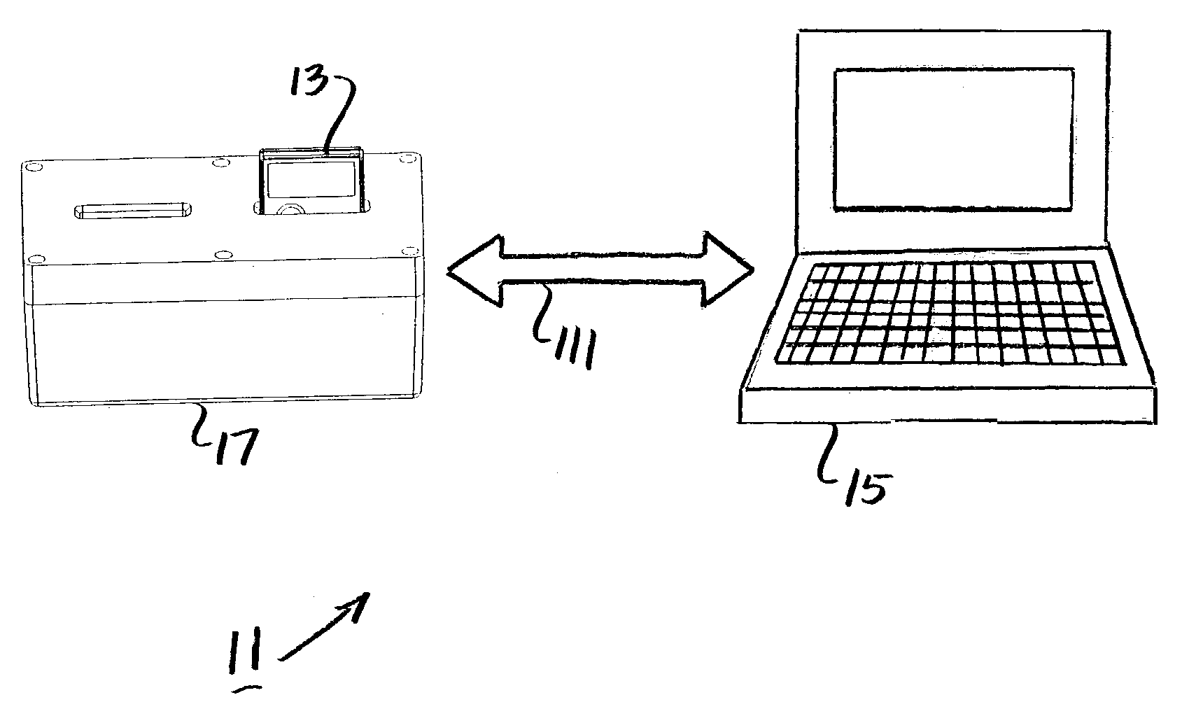
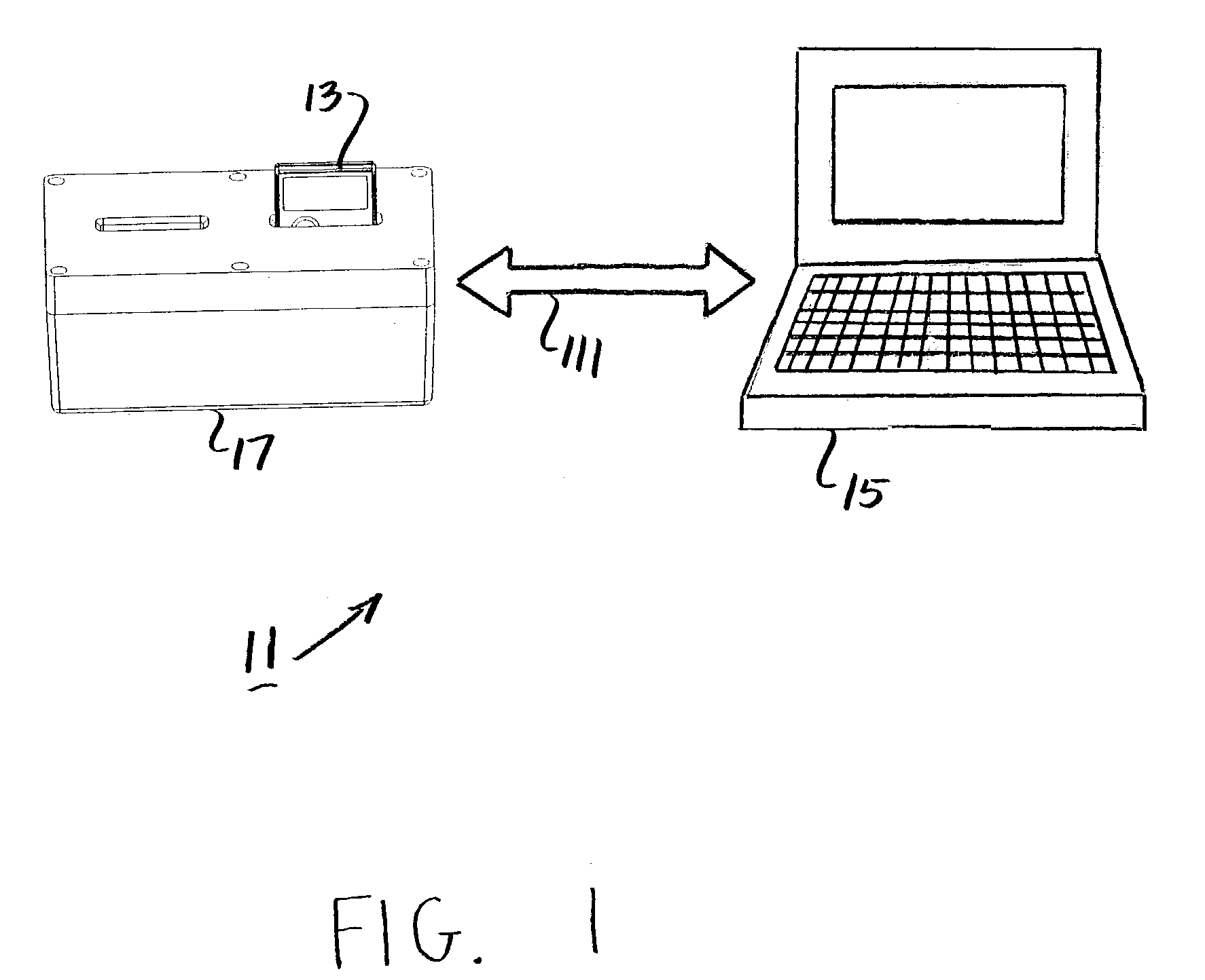
Although somewhat more helpful, this type of
data logger suffers from the same drawback as the previous
data logger in that its full analysis can only be performed by linking it to a PC, a cumbersome and
time consuming task for the receiving party.
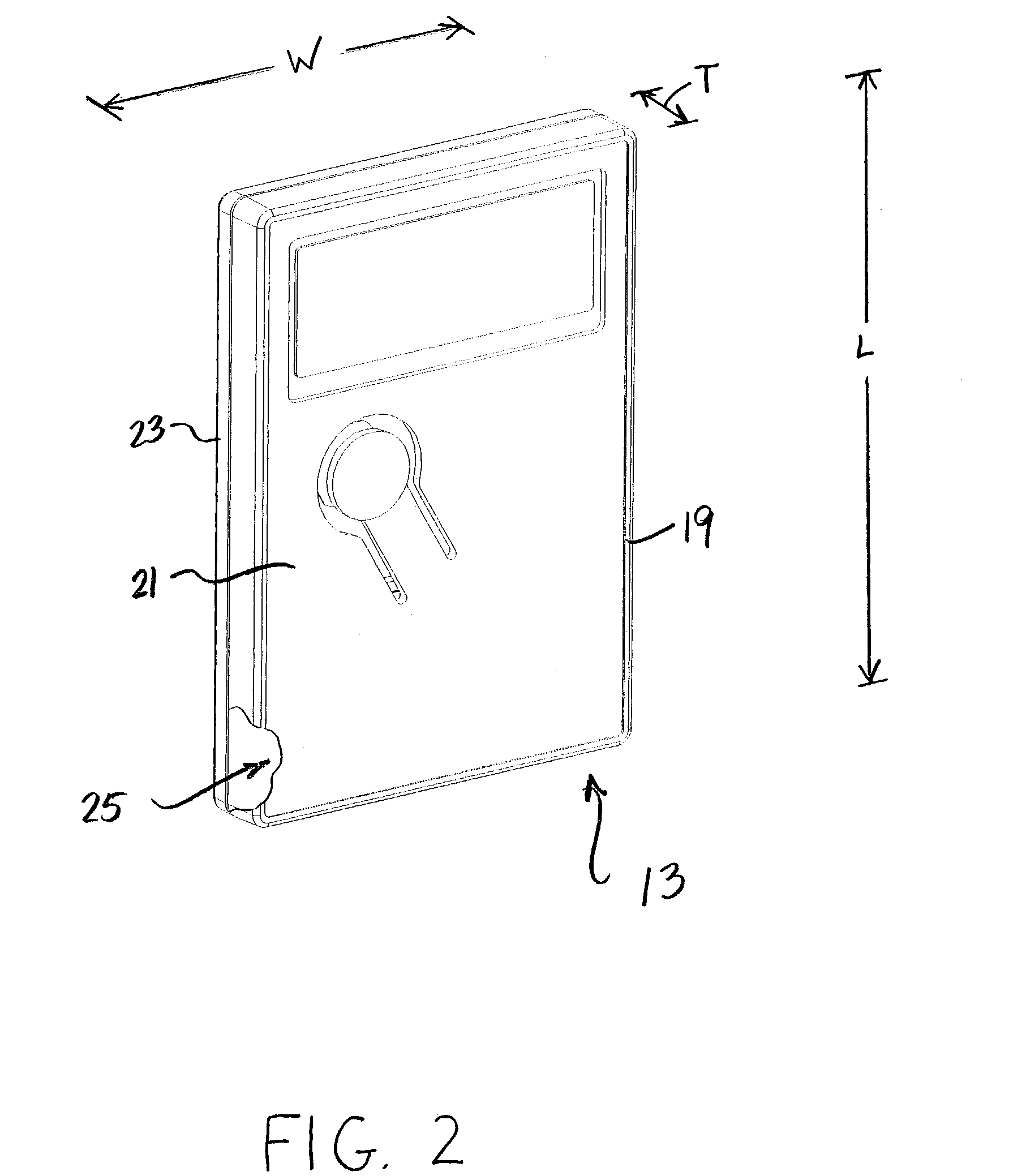
As a first drawback, the third type of data logger described above stores all of its accumulated historical data into its
internal memory.
Because all of the historical data is stored into the data logger memory, it is often difficult to view by means of its LCD the most
relevant information stored in the data logger (e.g., data relating to a temperature excursion).
As a second drawback, the third type of data logger described above includes large data storage capabilities.
As a result, this type of data logger is often relatively large in size, heavy in weight, and expensive to manufacture.
As a third drawback, the third type of data logger described above is highly susceptible to tampering and manipulation.

