Apparatus and method for E-beam dark field imaging

a dark field and electron beam technology, applied in material analysis using wave/particle radiation, instruments, nuclear engineering, etc., can solve the problems of higher lens aberration coefficient, inferior image resolution, and interference with the collection efficiency of below-the-lens detectors

Active Publication Date: 2006-11-28
KLA TENCOR TECH CORP
View PDF6 Cites 63 Cited by
  • Summary
  • Abstract
  • Description
  • Claims
  • Application Information

AI Technical Summary

Problems solved by technology

Unfortunately, immersion objective lens technology interferes with the collection efficiency of below-the-lens detectors 104.
Thus, non-immersion objective lens designs are typically used, resulting in higher lens aberration coefficients and leading to inferior image resolution.
In addition, the polar angle discrimination threshold is not well controlled for such below-the-lens detectors 104 because the electron energy and emission azimuth can affect the polar angle acceptance of the detector 104.
The behind-the-lens configuration 300 allows the use of immersion objective lens technology, but unfortunately the behind-the-lens configuration 300 typically has poor polar angle discrimination.
Immersion lens technology can be used with this approach, but the approach is sensitive to beam scanning and provides only poor azimuth discrimination and little or no polar angle discrimination.

Method used


Image

  • Apparatus and method for E-beam dark field imaging
  • Apparatus and method for E-beam dark field imaging
  • Apparatus and method for E-beam dark field imaging

Examples


Embodiment Construction

[0020]It is desirable to provide an SEM system with dark-field and bright-field imaging capabilities. It is further desirable for the system architecture to be designed to preserve the image resolution provided by an immersion lens without sacrificing dark-field image capability.

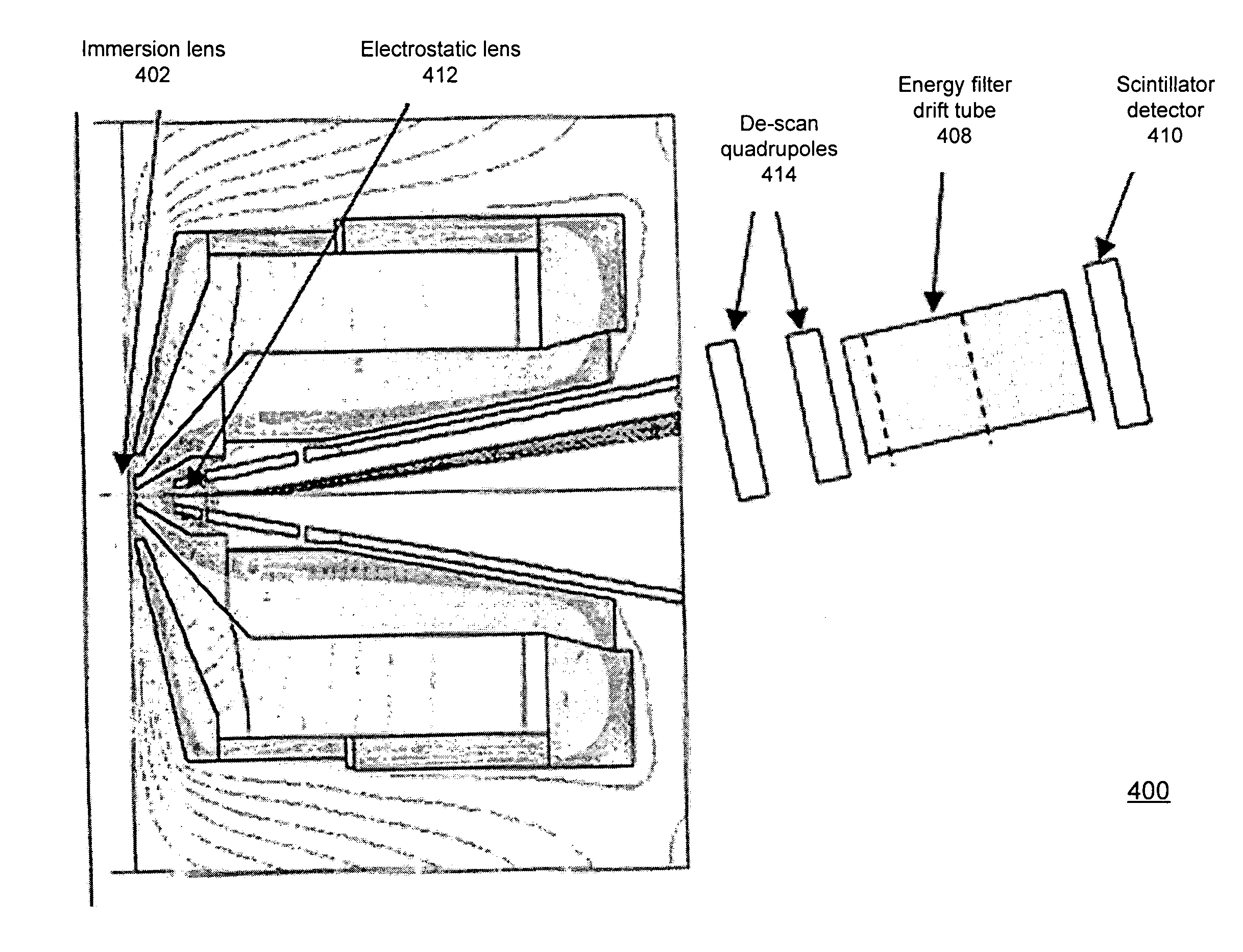
[0021]FIG. 4 is a diagram of an SEM dark field imaging system 400 with an improved behind-the-lens detection configuration in accordance with an embodiment of the invention. For purposes of explanation of the figure, certain components of the system are pointed to specifically. At the bottom of the figure, the immersion lens pole pieces 402 are shown. Next going up the column are the scan plates 404 and Wien filter 406. Towards the top, a scintillator detector 410 is shown, with an energy filter component 408 in front of the detector 410.

[0022]Depicted in FIG. 4 are various select components, including an immersion objective lens 402, an electrostatic lens 412, de-scan quadrupole lenses 414, the energy filte...


PUM

PropertyMeasurementUnit
voltageaaaaaaaaaa
voltageaaaaaaaaaa
polar anglesaaaaaaaaaa

Abstract

One embodiment disclosed relates to a scanning electron beam apparatus including an objective lens, scan deflectors, de-scan deflectors, an energy-filter drift tube, and a segmented detector. The objective lens may be an immersion lens configured with a high extraction field so as to preserve azimuthal angle discrimination of the electrons scattered from the specimen surface. The de-scan deflectors may be used to compensate for the scanning of the incident electron beam. The energy-filter drift tube is configured to align the scattered electrons according to polar angles of trajectory from the specimen surface.

Description

BACKGROUND OF THE INVENTION[0001]1. Field of the Invention[0002]The present invention relates to apparatus and methods for electron beam imaging.[0003]2. Description of the Background Art[0004]The two most common types of electron microscopes available commercially are the scanning electron microscope (SEM) and the transmission electron microscope (TEM). In an SEM, the specimen is scanned with a focused beam of electrons which produce secondary and / or backscattered electrons as the beam hits the specimen. These are detected and typically converted into an image of the surface of the specimen. Specimens in a TEM are examined by passing the electron beam through them, revealing more information of the internal structure of specimens.[0005]Bright field imaging and dark field imaging are often used in the context of TEMs. A bright field image may be formed in a TEM by selecting electrons from a central diffraction spot to form the image. A dark field image may be formed in a TEM by sele...

Claims


Application Information

Patent Timeline
Patent Type & Authority Patents(United States)
IPC IPC(8): G01N23/00
CPCH01J37/05H01J37/244H01J37/265H01J37/28H01J2237/053H01J2237/15H01J2237/1536H01J2237/2446H01J2237/24485
Inventor MASNAGHETTI, DOUGLAS K.MUNRO, ERICTOTH, GABOR D.KEISTER, JEFFREY
Owner KLA TENCOR TECH CORP
Why Eureka
Try Eureka