Particle beam irradiation system

a particle beam and irradiation system technology, applied in the field can solve the problems of reducing unable to continue treatment of patients using ion beam, and unable to continue ri production, so as to increase the availability factor of particle beam irradiation system, shorten the shutdown period of particle beam irradiation system, and increase the availability factor of particle beam irradiation

Active Publication Date: 2006-11-28
HITACHI LTD
View PDF9 Cites 111 Cited by
  • Summary
  • Abstract
  • Description
  • Claims
  • Application Information

AI Technical Summary

Benefits of technology

[0009]Accordingly, it is an object of the present invention to provide a particle beam irradiation system capable of increasing an availability factor.
[0011]Thus, the charged particle beam extracted from the one first accelerator can be introduced to one of the radioactive isotope production equipment and the second accelerator with the switching operation of the beam path switching unit, and the charged particle beam extracted from the other first accelerator can be introduced to the other of the radioactive isotope production equipment and the second accelerator with the switching operation of the beam path switching unit. Further, when one of the one first accelerator and the other first accelerator comes into an abnormal state, the charged particle beam can be selectively introduced to the radioactive isotope production equipment and the second accelerator from the remaining normal first accelerator. The first accelerator in the abnormal state can be checked while continuing the operation of the remaining normal first accelerator, whereby a shutdown period of the particle beam irradiation system can be shortened. It is therefore possible to increase the availability factor of the particle beam irradiation system.
[0012]With the present invention, since the first accelerator in the abnormal state can be checked while the remaining normal first accelerator is operated, the availability factor of the particle beam irradiation system can be increased.

Problems solved by technology

Therefore, the treatment for patients using the ion beam cannot be continued.
In addition, the RI production also cannot be continued and the diagnosis using the PET drug must be stopped.

Method used


Image

  • Particle beam irradiation system
  • Particle beam irradiation system
  • Particle beam irradiation system

Examples


Embodiment Construction

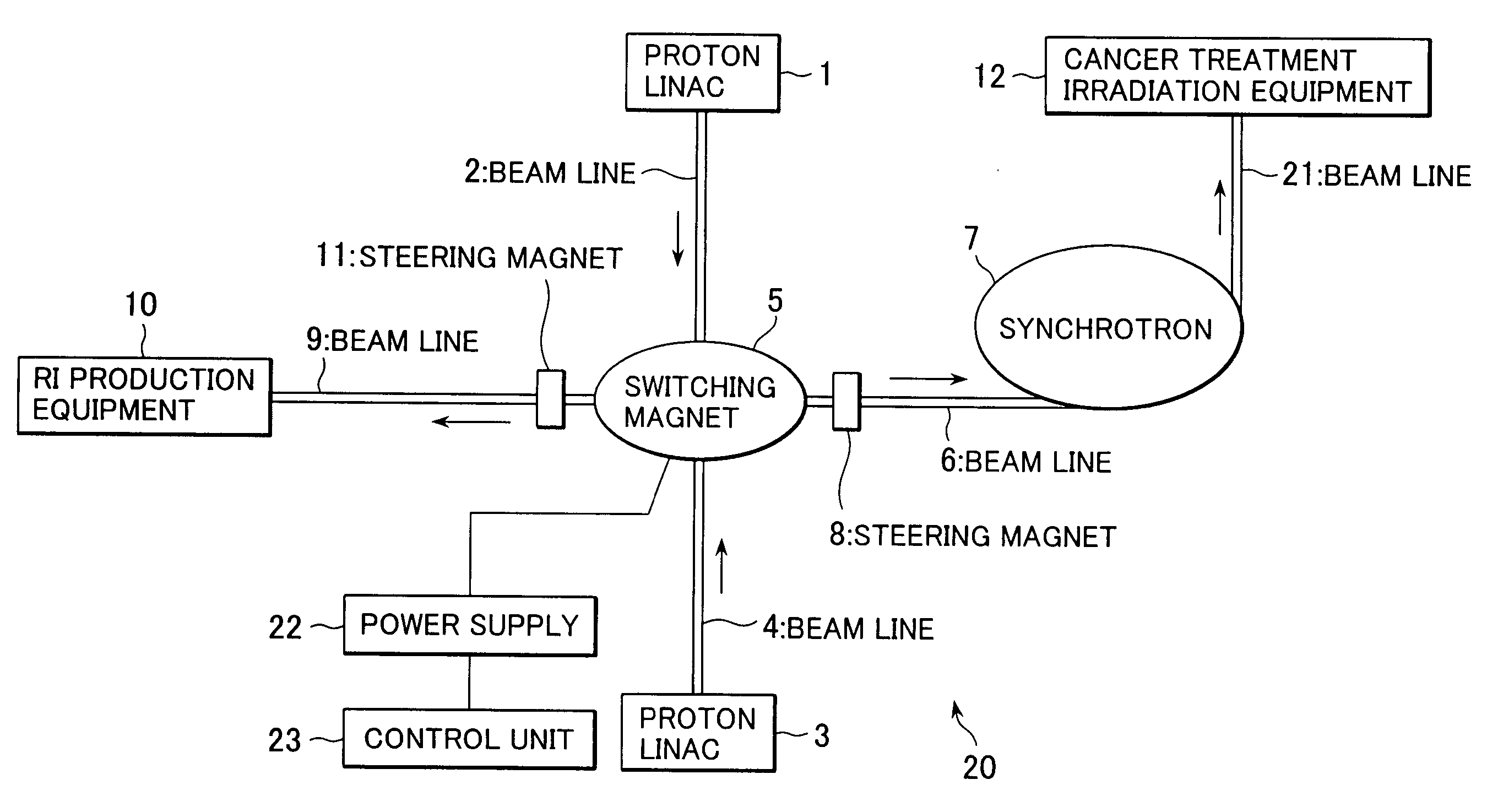
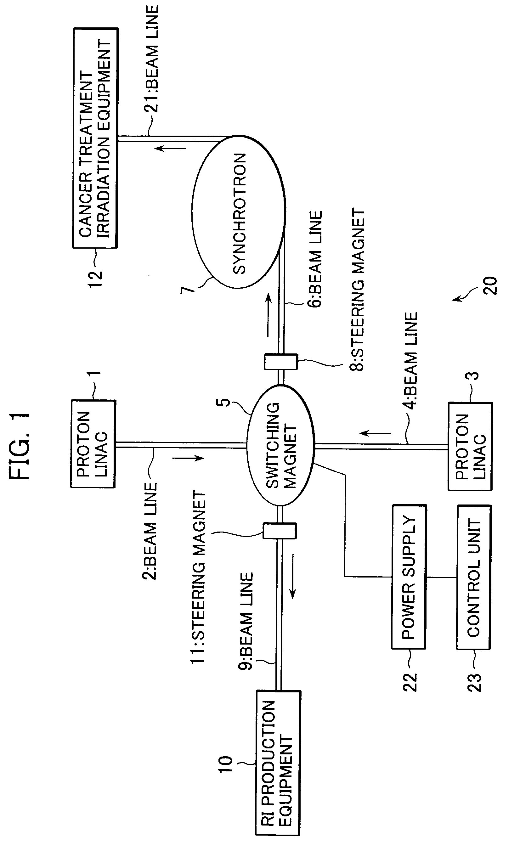
[0017]A proton beam irradiation system, i.e., one kind of a particle beam irradiation system, according to one preferred embodiment of the present invention will be described below with reference to FIGS. 1–3. A proton beam irradiation system 20 of this embodiment comprises proton beam linacs (linear accelerator) 1, 3, a switching magnet 5, a unit of radioactive isotope production equipment (hereinafter referred to as a “RI production equipment”) 10, a synchrotron 7, and a unit of irradiation equipment 12. Each of the proton beam linacs 1, 3 produces a proton beam of about 5–10 MeV. The proton beam linac 1 serving as a pre-stage accelerator is communicated with a beam line 2. The proton beam linac 3 is communicated with a beam line 4. A beam line 9 is communicated with the RI production equipment 10. A beam line 6 is communicated with the synchrotron 7. The synchrotron 7 serving as a main accelerator is communicated with the irradiation equipment 12 through a beam line 21. A steerin...


PUM


Abstract

A particle beam irradiation system which can increase an availability factor. An ion beam extracted from one proton beam linac is bent at 90 degrees by a switching magnet and is introduced to RI production equipment through a beam line. In the RI production equipment, a RI is produced using the introduced ion beam. An ion beam extracted from the other proton beam linac is bent at 90 degrees by the switching magnet and is introduced to a synchrotron through a beam line. The ion beam extracted from the synchrotron is irradiated to a patient from irradiation equipment. If one proton beam linac comes into an abnormal state, the one proton beam linac is stopped in operation and checked. During the check, the ion beam extracted from the other proton beam linac is selectively introduced to the RI production equipment and the synchrotron by the switching magnet.

Description

BACKGROUND OF THE INVENTION[0001]1. Field of the Invention[0002]The present invention relates to a particle beam irradiation system. More particularly, the present invention relates to a particle beam irradiation system suitably used in not only inspection employing equipment of Positron Emission Tomography (hereinafter abbreviated to “PET”) for producing a radioactive isotope (RI), e.g., fluorine 18, which is employed in a radioactive drug (hereinafter referred to as a “PET drug”) and applied to a patient (subject) going to take the inspection, but also in treatment of cancers.[0003]2. Description of the Related Art[0004]As known in the art, proton-beam cancer treatment equipment used for treatment of cancers employs an ion beam accelerating system including a linear accelerator (linac) having an acceleration capability in the range of several to 10 MeV as a beam introducing unit and a synchrotron, or an ion beam accelerating system including a cyclotron. On the other hand, in equi...

Claims


Application Information

Patent Timeline
Patent Type & Authority Patents(United States)
IPC IPC(8): G21K5/10H05H9/00
CPCG21K5/04H05H7/04
Inventor KAKIUCHI, LEGAL REPRESENTATIVE, AKIKOUMEGAKI, KIKUOHIRAMOTO, KAZUOKAKIUCHI, DECEASED, SHUNJI
Owner HITACHI LTD
Why Eureka
Try Eureka