Helix radiating elements for high power applications

Active Publication Date: 2006-11-28
LOCKHEED MARTIN CORP
View PDF5 Cites 9 Cited by
  • Summary
  • Abstract
  • Description
  • Claims
  • Application Information

AI Technical Summary

Benefits of technology

[0007]The present invention improves the power handling capability of radiating elements. In one embodiment, a helix radiating element is disclosed. The helix radiating element includes a support, a base and a helix wire. The support is made up of a dielectric material including PEEK (Polyetheretherketone), a dielectric with high temperature capability. The base is coupled to the PEEK support and is made up of boron nitride. Boron nitride is a low-loss, high temperature ceramic that is th

Problems solved by technology

The power handling capability of a helix radiating element is known to be limited by heating effects in the first several turns of the wire.
The li

Method used


Image

  • Helix radiating elements for high power applications
  • Helix radiating elements for high power applications
  • Helix radiating elements for high power applications

Examples


Embodiment Construction

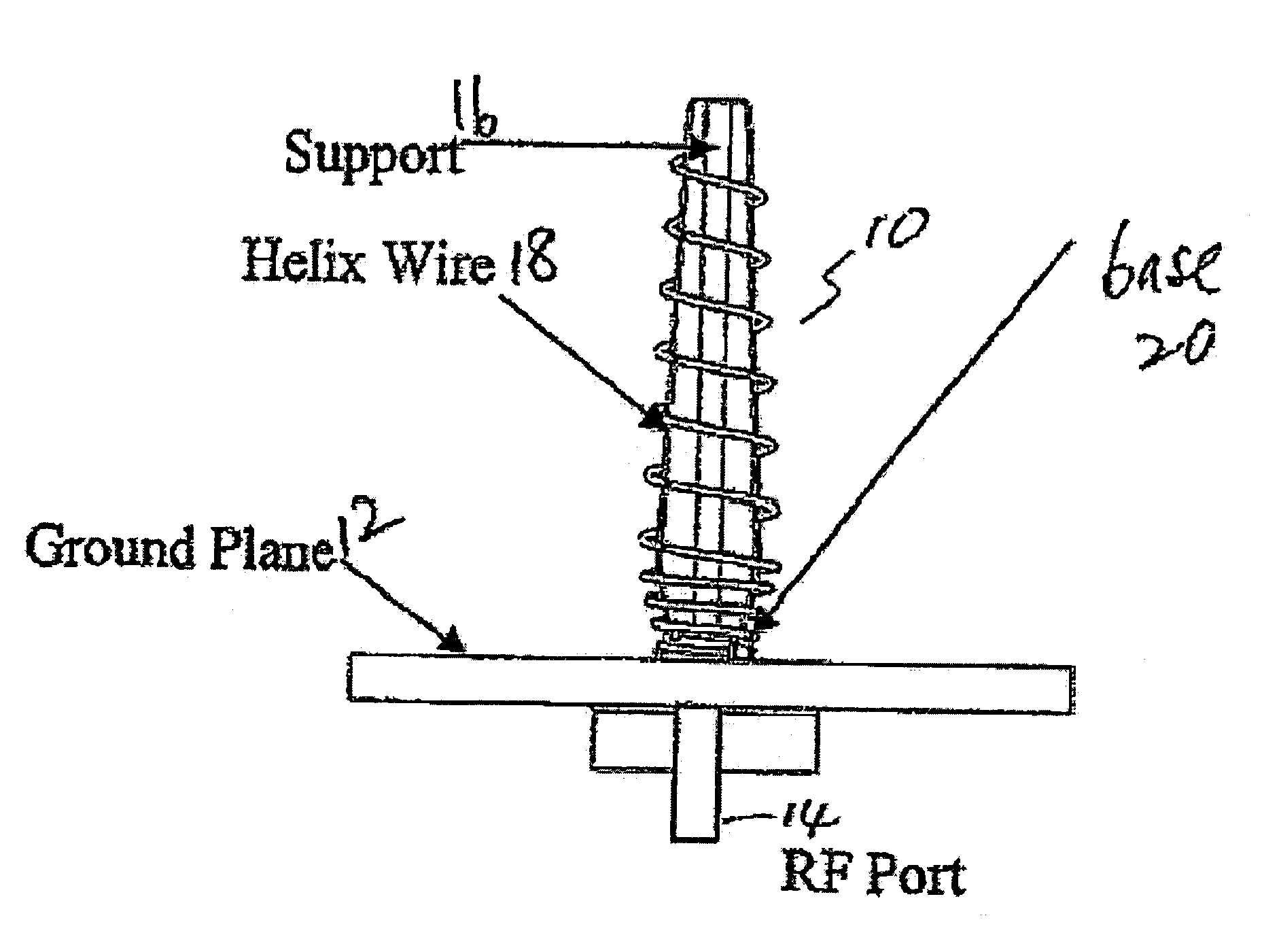
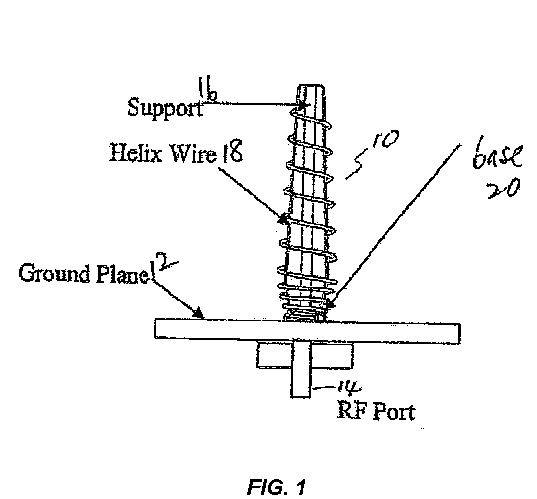
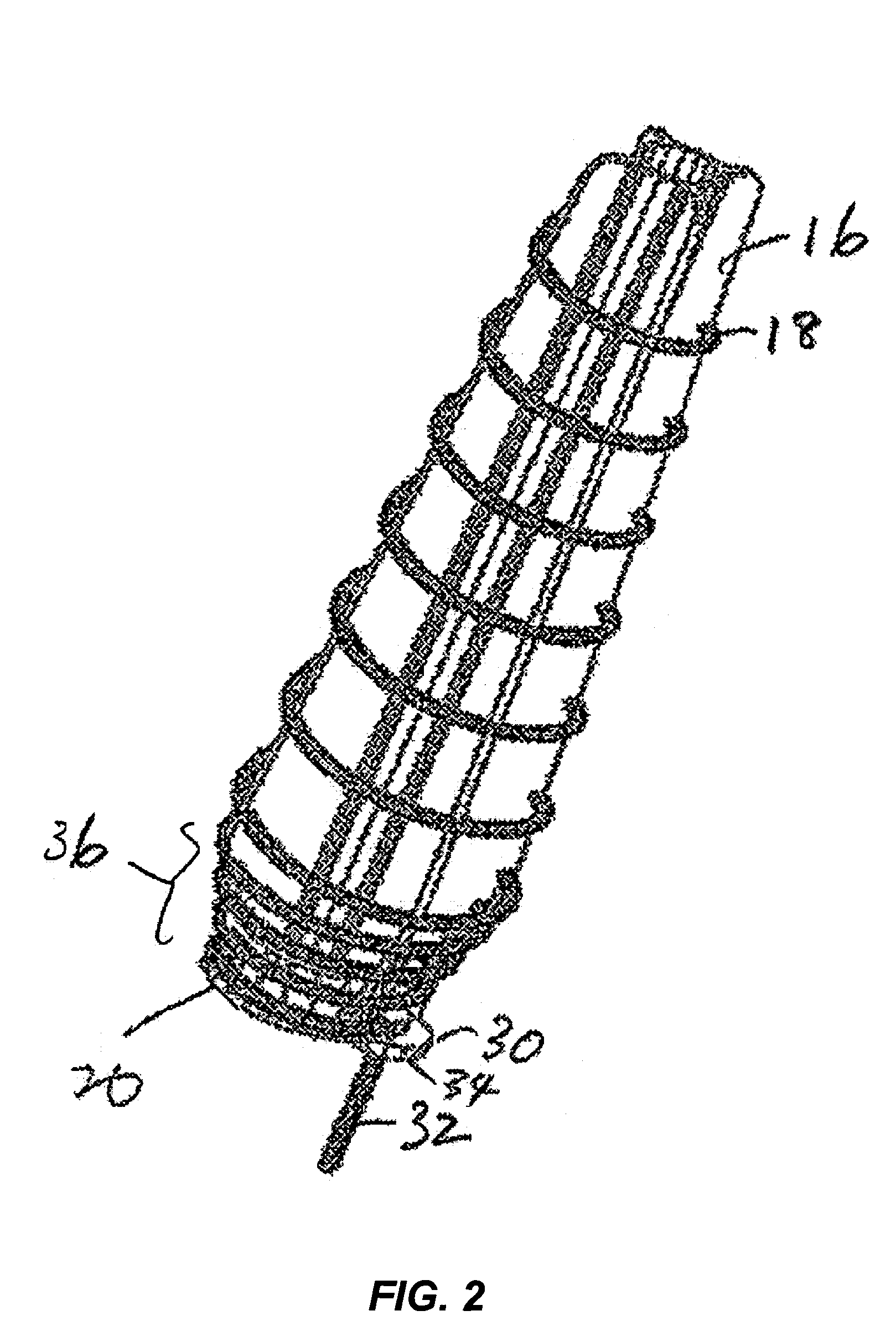
[0019]The present invention in the form of one or more exemplary embodiments will now be described. FIG. 1 illustrates one embodiment of a helix radiating element 10 coupled to a ground plane 12. The ground plane 12, in turn, is coupled to a RF (radio frequency) port 14. FIG. 2 further illustrates the helix radiating element 10 as shown in FIG. 1. The helix radiating element 10 includes a support 16, a helix wire 18 and a base 20, each of which will be further described below.

[0020]FIG. 3 illustrates the support 16 in further detail. In one embodiment, the support 16 is machined as one integral piece. The support 16 has a central section 24 and a number of panel sections 26a–d. A number of grooves or notches 22 are located along the edge of each of the panel sections 26a–d. The grooves 22 are machined at precise locations along the edges to enable the helix wire 18 to be wrapped around the support 16 in a precise geometrical configuration. By positioning the helix wire 18 in a preci...


PUM


Abstract

A helix radiating element is disclosed. The helix radiating element includes a support, a base and a helix wire. The support is made up of a dielectric material including a PEEK (Polyetheretherketone) material. The base is coupled to the support and is made up of boron nitride. The helix wire is configured to be wrapped around the support and bonded to the base. The base is coupled to a ground plane. A boron nitride filled adhesive is used to bond the support to the base and bond the helix wire to the base. The boron nitride filled adhesive is also used to bond the base to the ground plane. Heat generated in the helix wire is transferred to the ground plane via the base.

Description

CROSS-REFERENCES TO RELATED APPLICATION(S)[0001]Not Applicable.STATEMENT AS TO RIGHTS TO INVENTIONS MADE UNDER FEDERALLY SPONSORED RESEARCH OR DEVELOPMENT[0002]Not Applicable.BACKGROUND OF THE INVENTION[0003]The present invention generally relates to helix radiating elements, and more specifically, to methods and devices for providing helix radiating elements for high power applications.[0004]The power handling capability of a helix radiating element is known to be limited by heating effects in the first several turns of the wire. The limitation is usually in the dielectric that supports the wire. Currently, such limitation does not pose too much of a problem because the operating power levels are relatively low and common dielectrics are deemed to be sufficient for handling such power levels.[0005]As applications become more and more capacity driven, there is a corresponding increase in demand for transmission of high power. Traditional dielectrics may no longer be able to perform ...

Claims


Application Information

Patent Timeline
IPC IPC(8): H01Q1/36
CPCH01Q9/27
Inventor PATEL, KANTI N.CLARK, R. MARKMLYNARSKI, DENNISDAVIES, ROBERT G.
Owner LOCKHEED MARTIN CORP
Why Eureka
Try Eureka