Piston for internal combustion engine having high temperature-capable crown piece

a technology of internal combustion engine and crown piece, which is applied in the direction of machines/engines, manufacturing tools, mechanical apparatus, etc., can solve the problems of less predictable duty cycles, and achieve the effect of reducing temperature capability and high temperature capability

Active Publication Date: 2018-03-15
CATERPILLAR INC
View PDF6 Cites 0 Cited by
  • Summary
  • Abstract
  • Description
  • Claims
  • Application Information

AI Technical Summary

Benefits of technology

[0006]In one aspect, a piston for an internal combustion engine includes a compound piston body defining a longitudinal axis, and including a crown piece, a skirt piece, and a weld attaching the crown piece to the skirt piece. The crown piece includes a first axial end having a combustion bowl formed therein, and an annular piston rim extending circumferentially around the combustion bowl, and a second axial end including a first annular wall extending in a first axial direction. The skirt piece includes a first axial end having a second annular wall extending in a second axial direction, a second axial end that includes a piston skirt and a wrist pin bore formed therein. The weld extends circumferentially around the longitudinal axis, and axially between the first annular wall and the second annular wall. The compound piston body is formed of a lower temperature-capable steel throughout the skirt piece, and a higher temperature-capable steel throughout the crown piece. The higher temperature-capable steel has a martensitic microstructure and contains about 10% wt. or greater of chromium, and a balance of iron, carbon and optional alloying elements.
[0007]In another aspect, a piston for an internal combustion engine includes a compound piston body defining a longitudinal axis, and including a crown piece and a skirt piece. The crown piece includes a first axial end having a combustion bowl formed therein and an annular piston rim extending circumferentially around the combustion bowl. The crown piece further includes a second axial end having a first annular wall extending in a first axial direction. The skirt piece includes a first axial end having a second annular wall extending in a second axial direction, a second axial end that includes a piston skirt and a wrist pin bore formed therein. The crown piece has a higher temperature capability and is formed of a martensitic stainless steel, and the skirt piece has a lower temperature capability and is formed of a low alloy steel. The piston further includes a weld extending circumferentially around the longitudinal axis, and axially between the first annular wall and the second annular wall to form a bonded interface of the martensitic stainless steel and the low alloy steel attaching the crown piece to the skirt piece.
[0008]In still another aspect, a method of making a piston for an internal combustion engine includes positioning a crown piece formed of a martensitic stainless steel relative to a skirt piece formed of a low alloy steel such that a first annular wall of the crown piece is coaxially aligned with a second annular wall of the skirt piece. The method further includes contacting the crown piece to the skirt piece such that the first annular wall of the crown piece abuts the second annular wall of the skirt piece, and welding the crown piece and the skirt piece together to form a bonded interface of the martensitic stainless steel and the low alloy steel attaching the crown piece to the skirt piece.

Problems solved by technology

Still other engine duty cycles may be much less predictable, and the engine can operate for long periods of time at high idle, relatively long periods of time at low idle, and then be rapidly ramped up and ramped down between higher speeds and loads and lower speeds and loads for a period of time.

Method used


Image

  • Piston for internal combustion engine having high temperature-capable crown piece
  • Piston for internal combustion engine having high temperature-capable crown piece
  • Piston for internal combustion engine having high temperature-capable crown piece

Examples


Embodiment Construction

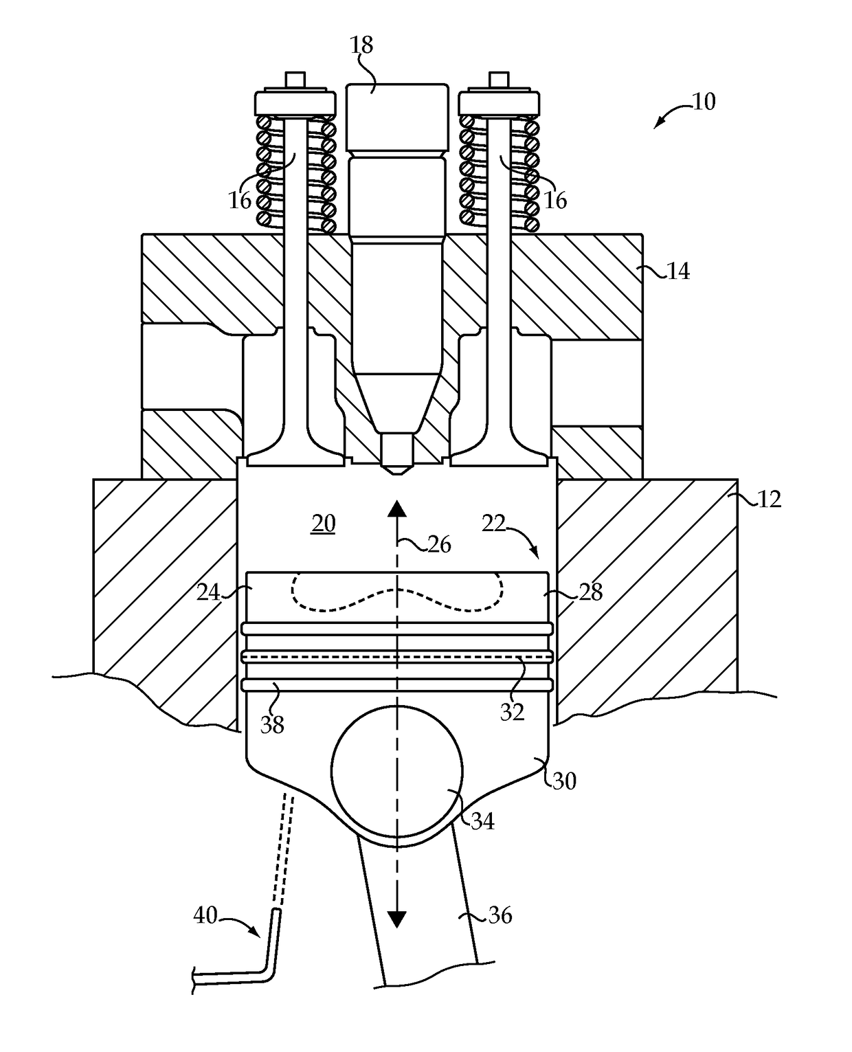
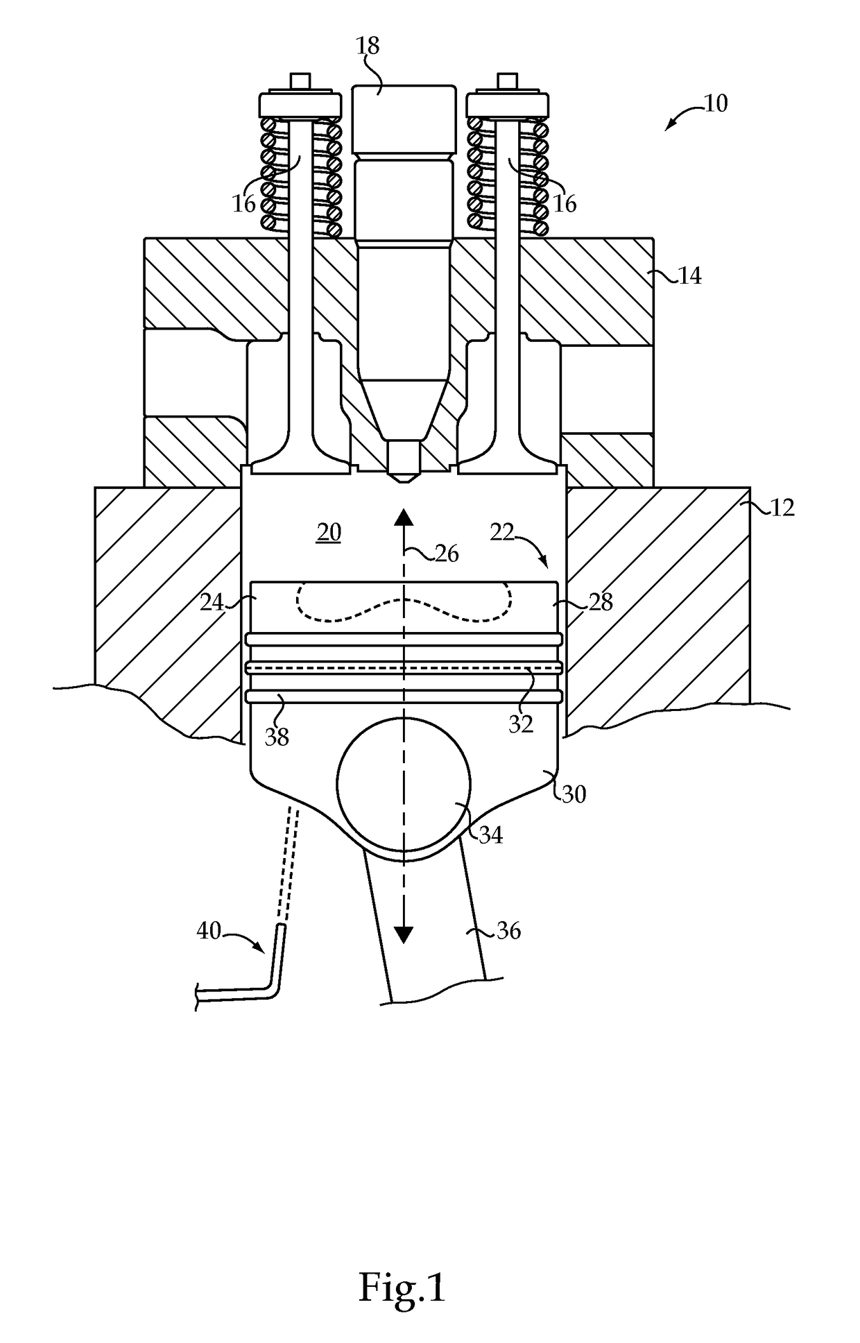
[0013]Referring to FIG. 1, there is shown an internal combustion engine 10 according to one embodiment. Internal combustion engine 10 (hereinafter “engine 10”) may be a compression ignition diesel engine, including an engine housing 12 and an engine head 14 coupled to engine housing 12. A plurality of gas exchange valves 16 may be positioned at least partially within engine head 14, and movable in a conventional manner to admit air into a cylinder 20 formed in engine housing 12, and permit exhaust to be expelled from cylinder 20, according to a conventional four-stroke engine cycle. In view of the illustration in FIG. 1, either one of gas exchange valves 16 could be understood as an intake valve or an exhaust valve. Engine 10 may further be direct injected, and to this end includes a fuel injector 18 positioned within engine head 14 and extending into cylinder 20 for direct injection of a fuel therein. Engine 10 will typically be a multi-cylinder engine, having 4, 6, 8, 10 or more e...


PUM

PropertyMeasurementUnit
temperaturesaaaaaaaaaa
diameteraaaaaaaaaa
diameteraaaaaaaaaa

Abstract

A piston for an internal combustion engine includes a compound piston body having a crown piece joined to a skirt piece by a circumferential weld. The skirt piece is formed of a lower temperature-capable steel such as a low alloy steel, and the crown piece is formed of a higher temperature-capable steel having a martensitic microstructure and containing about 10% wt. or greater of chromium. Related methodology for making a piston is also disclosed.

Description

TECHNICAL FIELD[0001]The present disclosure relates generally to a piston for an internal combustion engine, and more particularly to a compound piston body having a crown piece and a skirt piece formed of dissimilar materials and having improved temperature capability.BACKGROUND[0002]A great many different operating strategies and component designs are known from the field of internal combustion engines. Research and development has progressed for decades in relation to the manner in which factors such as fueling, exhaust gas recirculation, turbocharging, and variable valve actuation can be varied to produce different results. In addition to variation in these and other operating parameters, a great deal of research and testing effort has gone into the different ways that engine components, such as pistons, can be shaped and proportioned, and formed from various materials. One motivation driving advancements in combustion science and related research has been the desire to reduce r...

Claims


Application Information

Patent Timeline
Patent Type & Authority Applications(United States)
IPC IPC(8): F02F3/00F02F3/26F02F3/22B23K20/12B23K20/227C22C38/40
CPCF02F3/003F02F3/26F02F3/0084F02F3/22B23K20/129C21D2211/008C22C38/40F02F2003/0061B23K2201/003B23K2203/05B23K2203/04B23K20/227B23K2101/003B23K2103/05B23K2103/04
Inventor POLLARD, MICHAELKIZHAKKETHARA, INDRAJITHMCLEAN, HUGH
Owner CATERPILLAR INC
Why Eureka
Try Eureka