Hybrid turbine blade and related method

a hybrid turbine and blade technology, applied in the field of composite blades, can solve the problems of reducing reliability, blades contributing to higher disk stresses, and low performance, and achieve the effects of reducing the volume of filler, enhancing the cost benefit of this arrangement, and high temperature capability

Inactive Publication Date: 2006-02-02
GENERAL ELECTRIC CO
View PDF9 Cites 12 Cited by
  • Summary
  • Abstract
  • Description
  • Claims
  • Application Information

AI Technical Summary

Benefits of technology

[0005] This invention expands the hybrid blade concept to include the use of multiple fillers in a single blade or bucket as a function of required temperature capability. Typically, the higher temperature material would be used in the outermost radial pockets. Thus, the more costly and higher temperature capability material may be selected for use only in a limited area of the airfoil tip while the less expensive material may be selected in other areas, e.g., the radially inner or lower section of the blade airfoil. The cost benefit to this arrangement is further enhanced by the fact that a lesser volume of filler is required in the radially outer portions of the blade.

Problems solved by technology

This increasing section area of the blade at lower spans contributes to excessive flow blockage at the root and thus lower performance.
The weight of the blade contributes to higher disk stresses and thus to potentially reduced reliability.
Another issue relating to the use of hybrid steam turbine blades, however, relates to cost as a function of temperatures experienced by such blades during use.
Even during the operation of the water sprays, however, the cooling flow does not migrate to the heated area near the blade tips, and thus, cooling of the blade tips is minimal.
The blade tips during this condition can reach in excess of 400° F. wherein, during normal operation, the blade temperatures reach only about 150° F. Accordingly, most of the current polymers (urethanes and / or rubbers) considered for hybrid bucket applications are restricted for use at less than 300° F. While there are a few high temperature polymers available, their cost may be as much as 5× the cost of the lower temperature polymers.

Method used


Image

  • Hybrid turbine blade and related method
  • Hybrid turbine blade and related method
  • Hybrid turbine blade and related method

Examples


Embodiment Construction

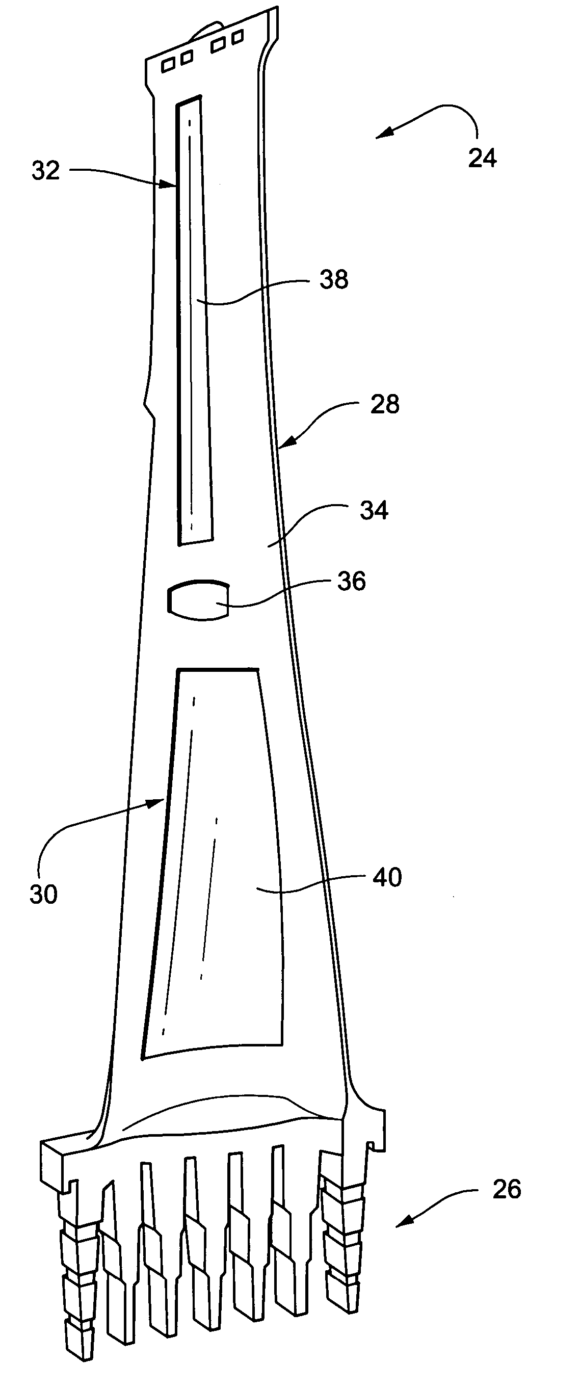
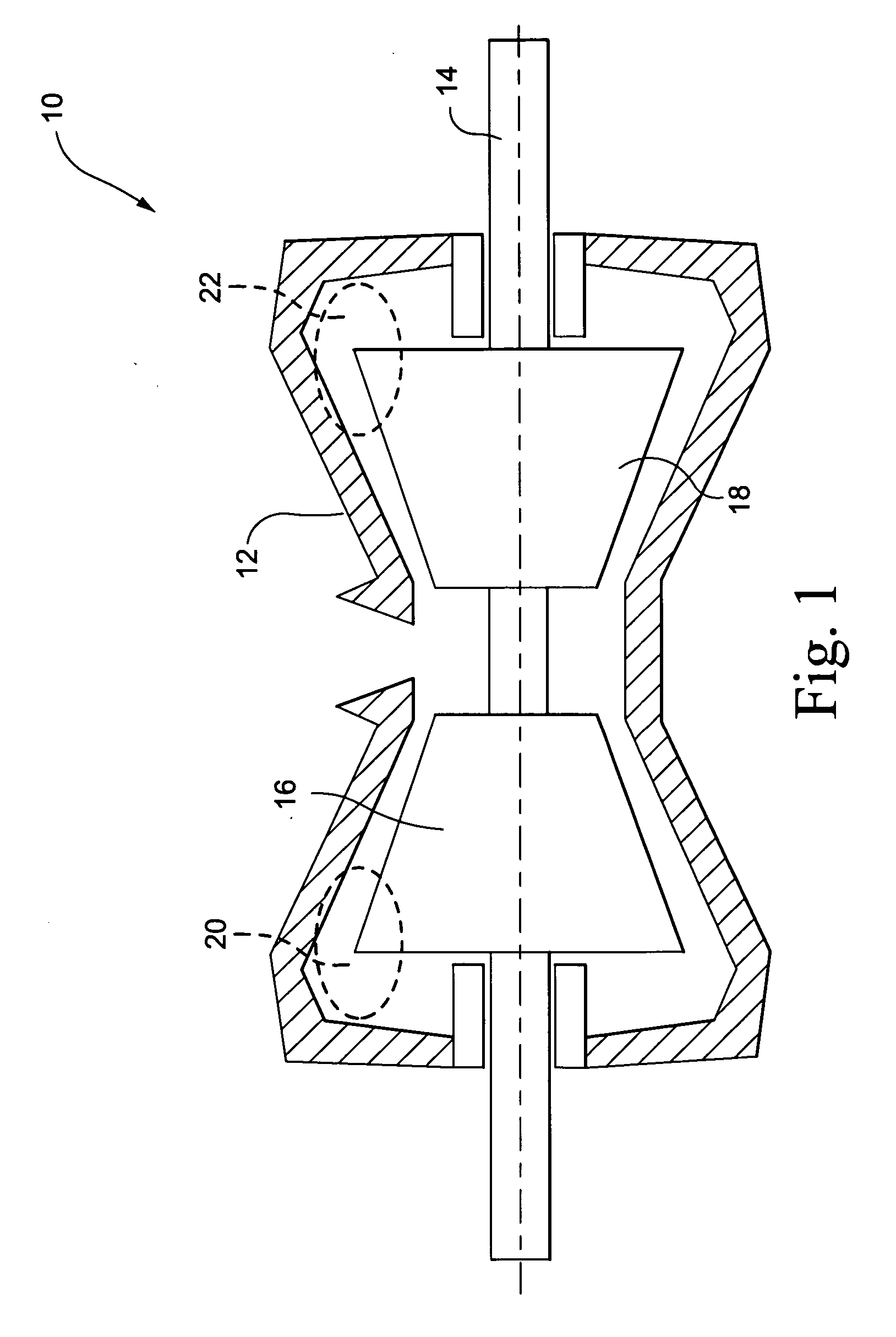
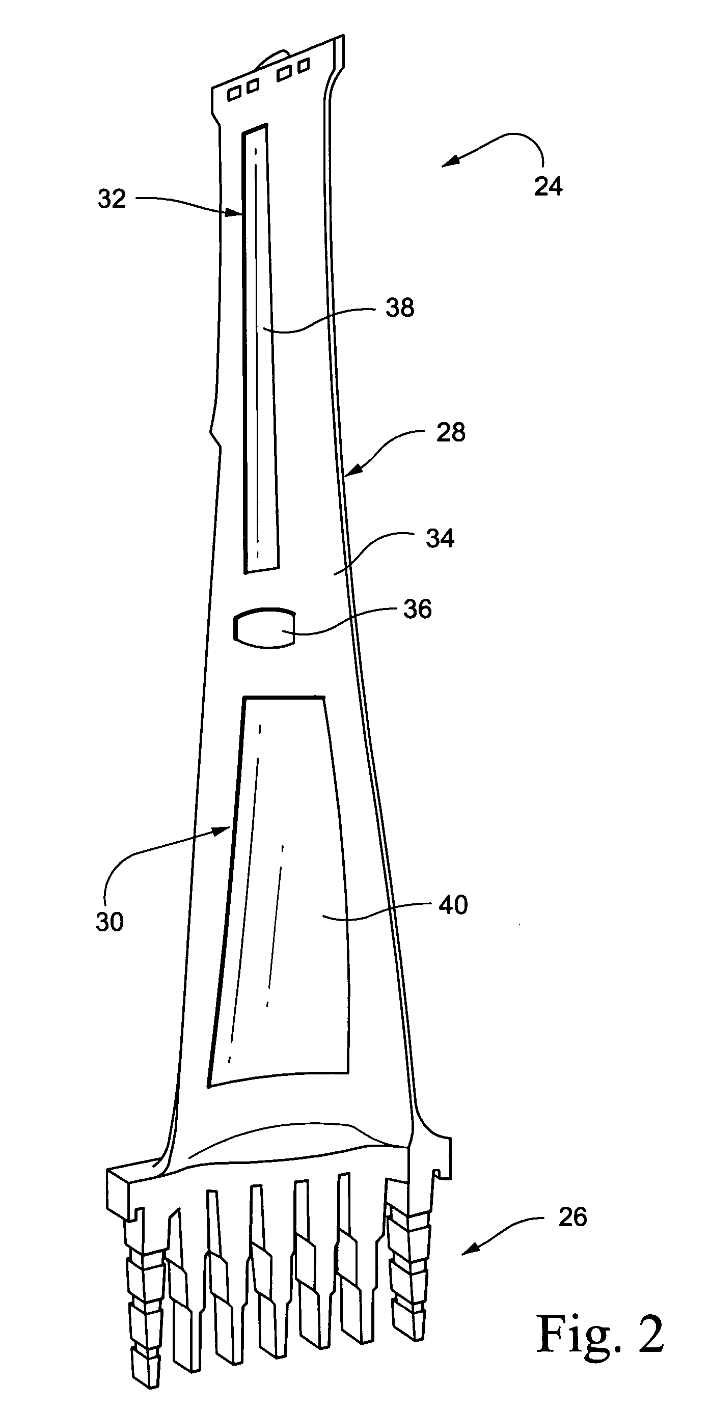
[0013]FIG. 1 shows a schematic diagram of a double-flow, low pressure turbine 10 including a turbine casing 12, rotor 14 and a plurality of wheels in two turbine sections indicated at 16, 18. The areas 20, 22 circled in dotted lines represent the radially outermost regions of the last stage blades that have been shown to experience the most windage heating during partial load conditions. Thus, in accordance with an exemplary embodiment of the invention, higher temperature filler material (at least 400° F. capability) is used in radially outer pockets of the blades. FIG. 2, for example, shows a blade 24 including a shank portion 26 and an airfoil portion 28. Radially inner and outer pockets 30, 32 are formed on the pressure side of the airfoil portion 28, separated by a relatively wide web or rib 34 and a mid-span damper 36. In the example given, a high temperature filler material 38 is used to fill pocket 32 and a lower temperature filler material 40 would be used to fill pocket 30....


PUM

PropertyMeasurementUnit
temperature capabilityaaaaaaaaaa
temperatureaaaaaaaaaa

Abstract

A method of manufacturing a blade for assembly on a steam turbine rotor wheel includes forming an airfoil portion with plural pockets and filling the pockets with more than one filler material chosen as a function of required temperature capability.

Description

BACKGROUND OF THE INVENTION [0001] This invention relates generally to steam turbine buckets (or blades) and, more particularly, to composite blades designed to provide different predetermined temperature capabilities in different selected areas of the airfoil portions of the blades. [0002] For turbine buckets or blades, centrifugal loads are a function of the operating speed, the mass of the blade, and the radius from engine centerline where that mass is located. As the mass of the blade increases, the physical area or cross-sectional area must increase at lower radial heights to be able to carry the mass above it without exceeding the allowable stresses for the given material. This increasing section area of the blade at lower spans contributes to excessive flow blockage at the root and thus lower performance. The weight of the blade contributes to higher disk stresses and thus to potentially reduced reliability. [0003] Several prior U.S. patents relate to so-called “hybrid” blade...

Claims


Application Information

Patent Timeline
Patent Type & Authority Applications(United States)
IPC IPC(8): B63H1/26
CPCF01D5/147Y10T29/49337Y02T50/672Y02T50/60F01D5/00F01D5/28
Inventor BURDGICK, STEVEN SEBASTIANDELEONARDO, GUY W.LIN, WENDY W.LANAUD, CHRISTOPHE
Owner GENERAL ELECTRIC CO
Why Eureka
Try Eureka