Turbine blade attachment lightening holes

a technology of turbine blades and lightening holes, which is applied in the field of turbine blades, can solve the problems of increased creep capability, lower component life, and higher stress, and achieve the effects of improving creep resistance, maintaining mechanical load and stress levels

Inactive Publication Date: 2005-10-25
ANSALDO ENERGIA SWITZERLAND AG
View PDF8 Cites 5 Cited by
  • Summary
  • Abstract
  • Description
  • Claims
  • Application Information

AI Technical Summary

Benefits of technology

[0007]The turbine blade in accordance with the preferred embodiment of the present invention is uncooled and cast from a high density nickel base alloy with high temperature capability. The material, while having a higher density than alloys used in prior art turbine blades, also has the benefit of a higher creep capability, or resistance to creep, for the airfoil section of the turbine blade. However, the increase in creep capability does not come without a drawback. The higher density of the alloy, for the same blade structure, has a greater weight, and therefore results in a greater radial pull or load on the turbine blade attachment and corresponding turbine blade disk. The greater load applied to the turbine blade attachment and turbine blade disk results in higher stresses and lower component life. The present invention compensates for this load increase, and corresponding higher stress, by incorporating a plurality of first cavities that extend generally radially outward from the bottom of the attachment, through the neck, and terminating radially inward of the platform. These first cavities remove excess material from the blade attachment and neck regions, which lowers the overall weight of the turbine blade, and its corresponding load on the turbine disk, when in operation. The first cavities terminate radially inward of the platform so as to not adversely affect the load carrying area of the airfoil. Geometric specifics regarding the plurality of first cavities are also disclosed.
[0009]It is an object of the present invention to provide a turbine blade having improved resistance to creep while maintaining mechanical load and stress levels on the interface region between a turbine blade attachment and mating turbine disk.

Problems solved by technology

However, the increase in creep capability does not come without a drawback.
The greater load applied to the turbine blade attachment and turbine blade disk results in higher stresses and lower component life.

Method used


Image

  • Turbine blade attachment lightening holes
  • Turbine blade attachment lightening holes
  • Turbine blade attachment lightening holes

Examples


Embodiment Construction

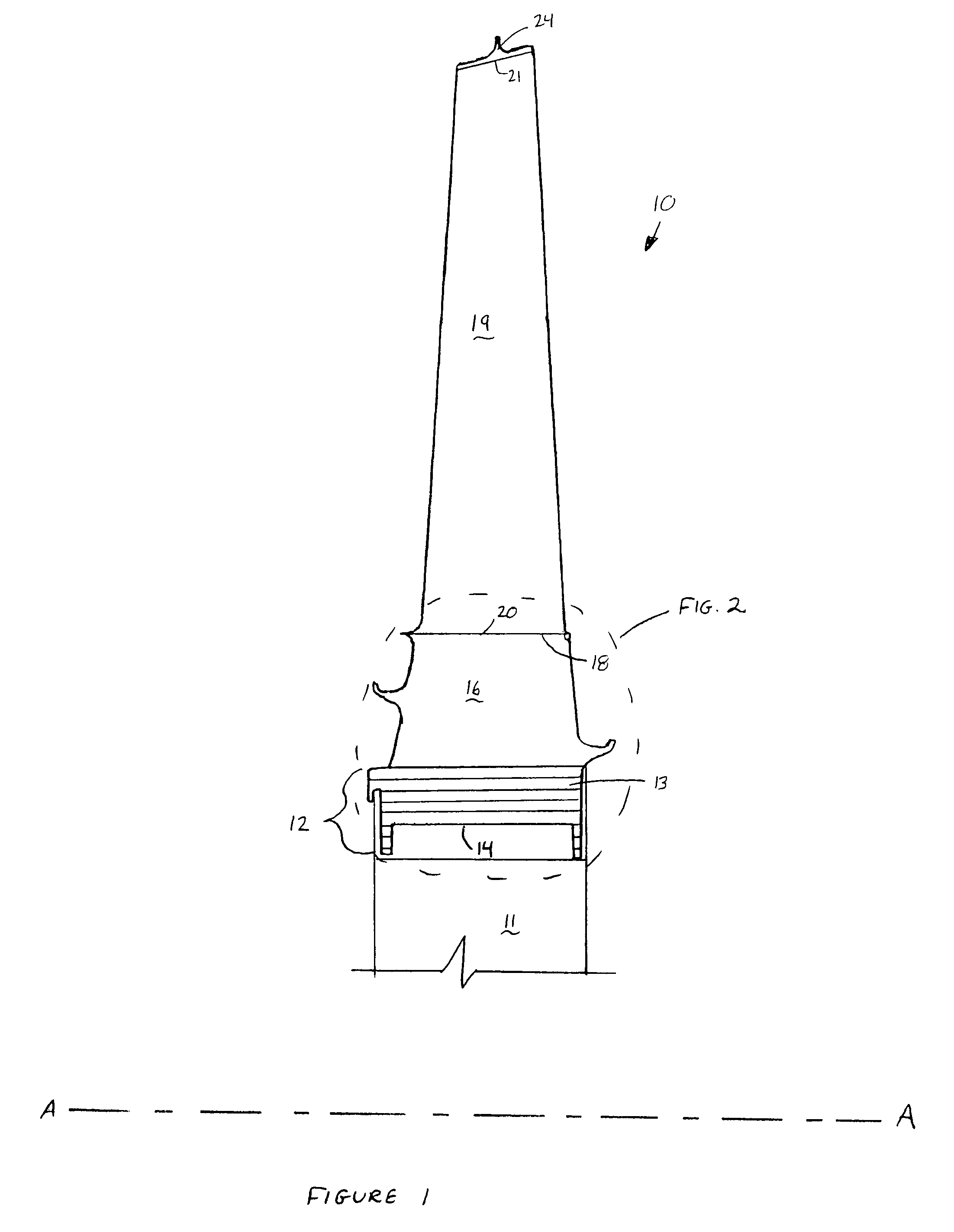
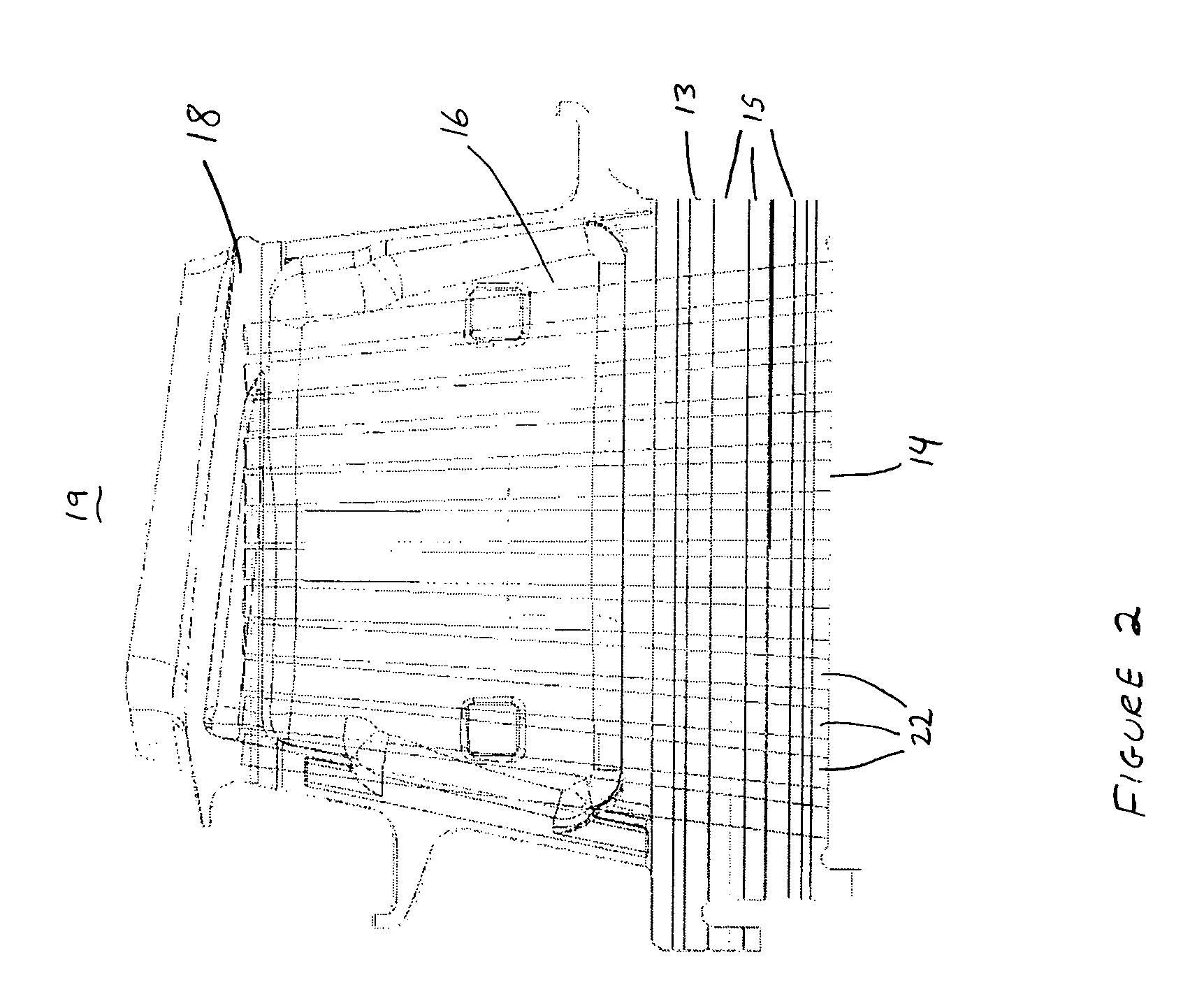
[0018]Referring to FIG. 1, a turbine blade 10, in accordance with the preferred embodiment, is shown in a portion of a turbine disk 11 for rotation about an axis A—A in a turbine section of a gas turbine engine. Turbine blade 10 has been configured to have an increased resistance to creep while generally maintaining operating stress levels at interface region 12 between turbine blade 10 and mating turbine disk 11.

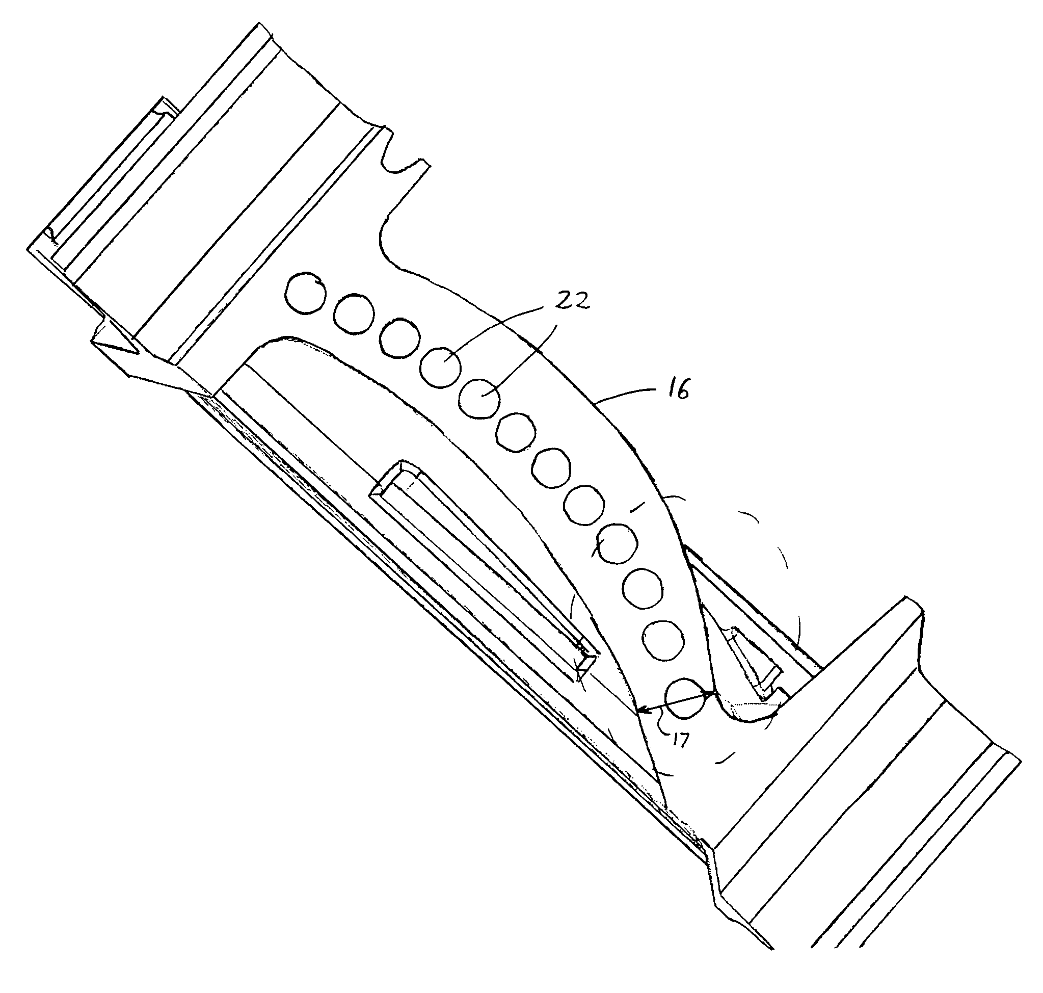
[0019]Referring now to FIGS. 1 and 2, turbine blade 10 comprises an attachment 13 having a generally planar first surface 14 parallel to axis A—A and a plurality of axially extending serrations 15 for engagement with turbine disk 11. Extending generally radially outward from and fixed to attachment 13 is neck 16, which has a region of minimum thickness 17 (see FIG. 3). Referring back to FIG. 1, a platform 18 is fixed to and extends generally radially outward from neck 16. Extending generally radially outward from platform 18 is an airfoil 19 having a first end 20 and a seco...


PUM


Abstract

The present invention seeks to provide a turbine blade with increased creep capability for both uncooled and cooled turbine blades while generally maintaining operating stress levels at an interface region between the turbine blade and a turbine disk. A turbine blade is disclosed having an attachment, a neck, a platform, and an airfoil. Extending radially outward from the attachment, through the neck, and terminating radially inward of the platform is a plurality of first cavities. The turbine blade in accordance with the preferred embodiment of the present invention is cast from a high density nickel base alloy with high temperature capability and improved creep capability. A plurality of first cavities are placed in the attachment and neck region to reduce excess weight of the turbine blade due to the higher density, greater creep capable alloy. Reducing the weight of the blade in this region provides increased creep capability in the turbine blade airfoil while maintaining operating stress levels.

Description

TECHNICAL FIELD[0001]This invention relates to turbine blades used in a gas turbine engine and more specifically to a turbine blade having improved resistance to creep while not adversely affecting the load on a turbine disk.BACKGROUND OF THE INVENTION[0002]A typical gas turbine engine contains an inlet, compressor, combustor, turbine, and exhaust duct. Air enters the inlet and passes through the compressor, with each successive stage of the compressor raising the pressure and temperature of the air. The compressed air mixes with fuel in the combustor and undergoes a chemical reaction to form hot combustion gases that pass through the turbine. The turbine, which contains a series of alternating stages of rotating blades and stationary vanes, is coupled to drive the compressor through a common rotor. As the hot combustion gases pass through the turbine, the thermal energy is converted into mechanical work by turning each stage of turbine blades that are contained within a disk, which...

Claims


Application Information

Patent Timeline
Patent Type & Authority Patents(United States)
IPC IPC(8): F01D5/18F01D5/14
CPCF01D5/147F01D5/18
Inventor BROOKS, TOMSELESKI, RICHARDCHURBUCK, THOMASBREW, JR., THOMAS E.
Owner ANSALDO ENERGIA SWITZERLAND AG
Why Eureka
Try Eureka