Large flattened mode tuned cladding photonic crystal fiber laser and amplifier

a photonic crystal fiber and tuned cladding technology, applied in the direction of instruments, optical light guides, optical waveguide light guides, etc., can solve the problems of insufficient discrimination between the fundamental mode and the higher order modes during amplification, the loss differential between the modes becomes so small, and the signal in the core of a single-mode fiber also experiences loss

Inactive Publication Date: 2006-11-28
AIR FORCE THE GOVERNMENT OF THE UNITED STATES AS REPRESENTED BY THE SEC OF THE
View PDF4 Cites 61 Cited by
  • Summary
  • Abstract
  • Description
  • Claims
  • Application Information

AI Technical Summary

Problems solved by technology

The signal in the core of a single-mode fiber also experiences loss as a result of manufacturing irregularities and physical perturbations such as bending.
Above this diameter, however, the loss differential between the modes becomes so small that it does not sufficiently discriminate the fundamental mode from the higher order modes during amplification.
If larger area cores are sought, the tradeoff between fundamental mode loss and multi-mode operation is unavoidable if the cladding around the core is uniform, either in the sense of h

Method used


Image

  • Large flattened mode tuned cladding photonic crystal fiber laser and amplifier
  • Large flattened mode tuned cladding photonic crystal fiber laser and amplifier
  • Large flattened mode tuned cladding photonic crystal fiber laser and amplifier

Examples


Embodiment Construction

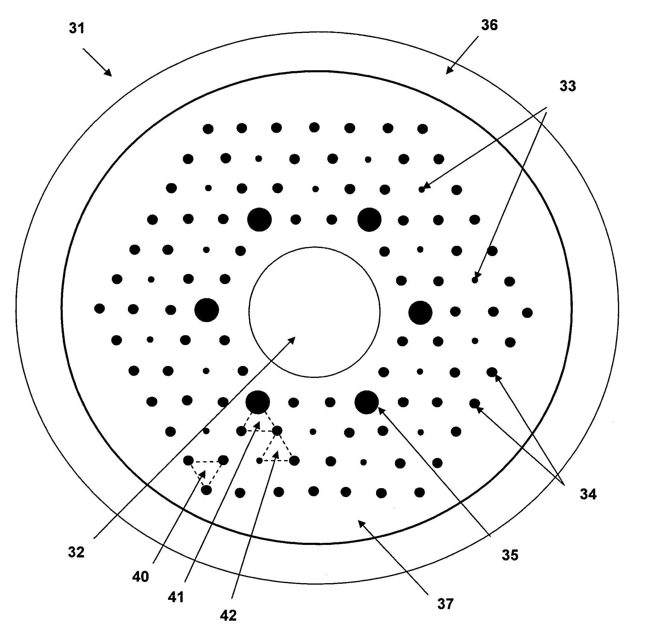
[0020]Computer simulations show that microstructures that guide a fundamental mode with an effective index matched to the effective index of the undesired higher-order modes will couple the power away from the undesired modes in the core. This is analogous to index matching at an optical boundary inhibiting reflection at that boundary. Different detailed microstructures may, therefore, be used for each of the different undesired modes in the core.

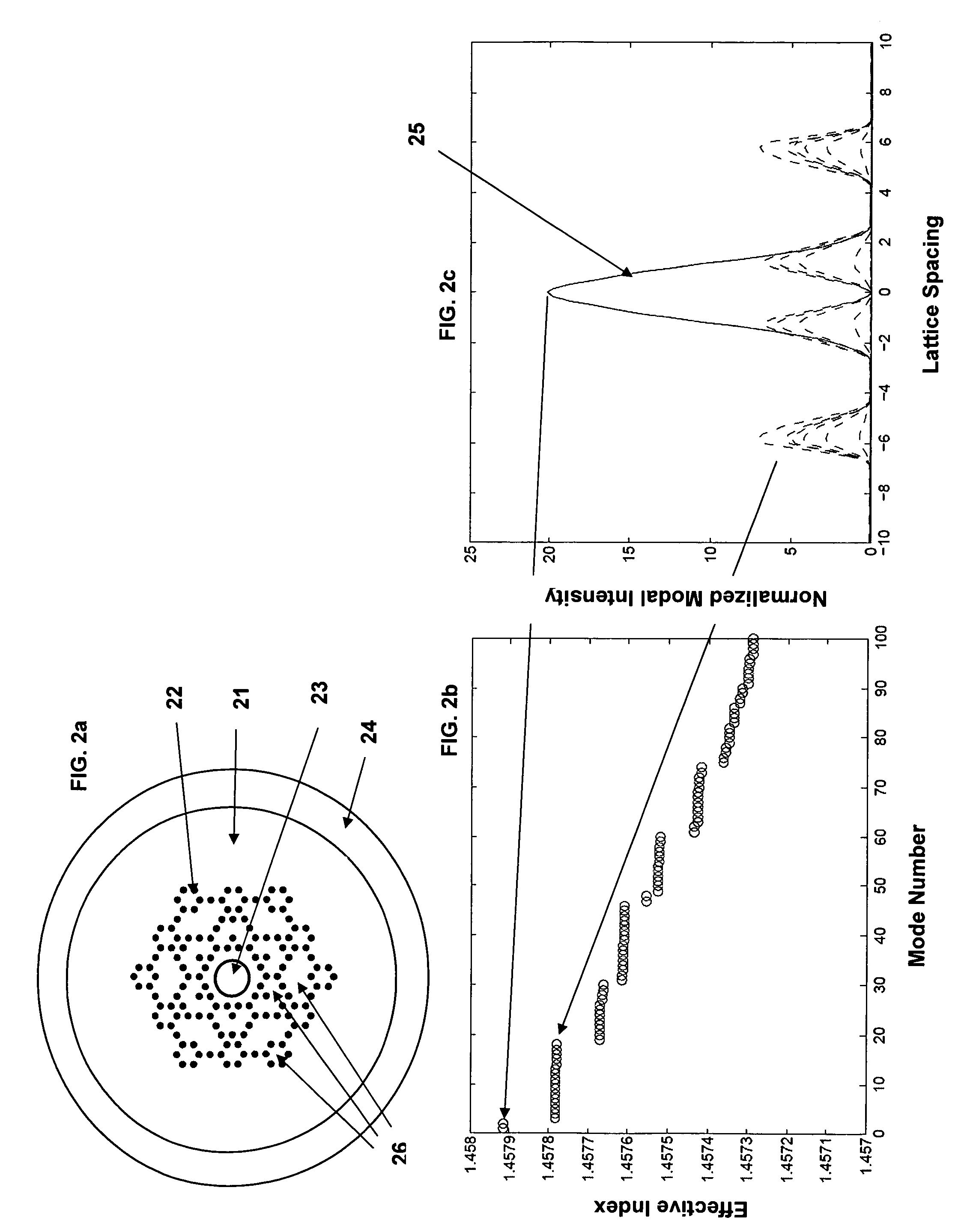
[0021]Increases in the core area are the subject of co-pending U.S. patent application Ser. No. 11 / 204,146 filed Aug. 15, 2005. FIG. 2a is a cross-section of a tuned cladding fiber example from the '146 application having an outer cladding layer 24 of uniform index of refraction n3. The inner cladding 21 is comprised of tuned cladding fiber material that has an average index of refraction of n23 that is either homogeneous (glass of index n1) or microstructured (glass tuned element areas 26 defined by missing or filled in air holes). In this...


PUM


Abstract

A modified photonic crystal fiber yielding a higher peak power for a given maximum intensity. The multi-mode signal core has a depressed index of refraction that pushes the mode distribution to the core edges while a pattern of larger air holes is used to flatten the mode distribution. The core is further surrounded by tuned cladding elements defined by a pattern of smaller air holes that cause loss in all of the core modes except the fundamental while maintaining robust guiding of the fundamental mode.

Description

STATEMENT OF GOVERNMENT INTEREST[0001]The conditions under which this invention was made are such as to entitle the Government of the United States under paragraph I(a) of Executive Order 10096, as represented by the Secretary of the Air Force, to the entire right, title and interest therein, including foreign rights.BACKGROUND OF THE INVENTION[0002]Fiber lasers and amplifiers make use of a dielectric waveguide, the fiber, to constrain the degrees of freedom of the electromagnetic field while it is amplified by excited laser atoms within the core of the fiber. Given an amplifying waveguide, a fiber laser is formed by introducing it into a resonant cavity. One of the main advantages of fiber lasers is that if a single transverse waveguide mode is present in the fiber, then the output will have diffraction limited beam quality. Only one type of dielectric waveguide is considered here, a modified total internal reflection photonic crystal fiber (MTIR PCF), also known as solid-core phot...

Claims


Application Information

Patent Timeline
IPC IPC(8): G02B6/032
CPCG02B6/02338G02B6/02347G02B6/02357G02B6/02019
Inventor WARD, BENJAMIN G.
Owner AIR FORCE THE GOVERNMENT OF THE UNITED STATES AS REPRESENTED BY THE SEC OF THE
Why Eureka
Try Eureka