
Optical fiber chirped pulse amplifier for ultra-short laser pulse output

A laser pulse and pulse output technology, applied in cladding fiber, optical waveguide light guide, optics, etc., can solve problems such as no good solution, and achieve good device stability, high anti-damage threshold, stable and reliable integration. Effect

Inactive Publication Date: 2010-11-10
SUZHOU UNIV
View PDF0 Cites 14 Cited by
  • Summary
  • Abstract
  • Description
  • Claims
  • Application Information

AI Technical Summary

Problems solved by technology

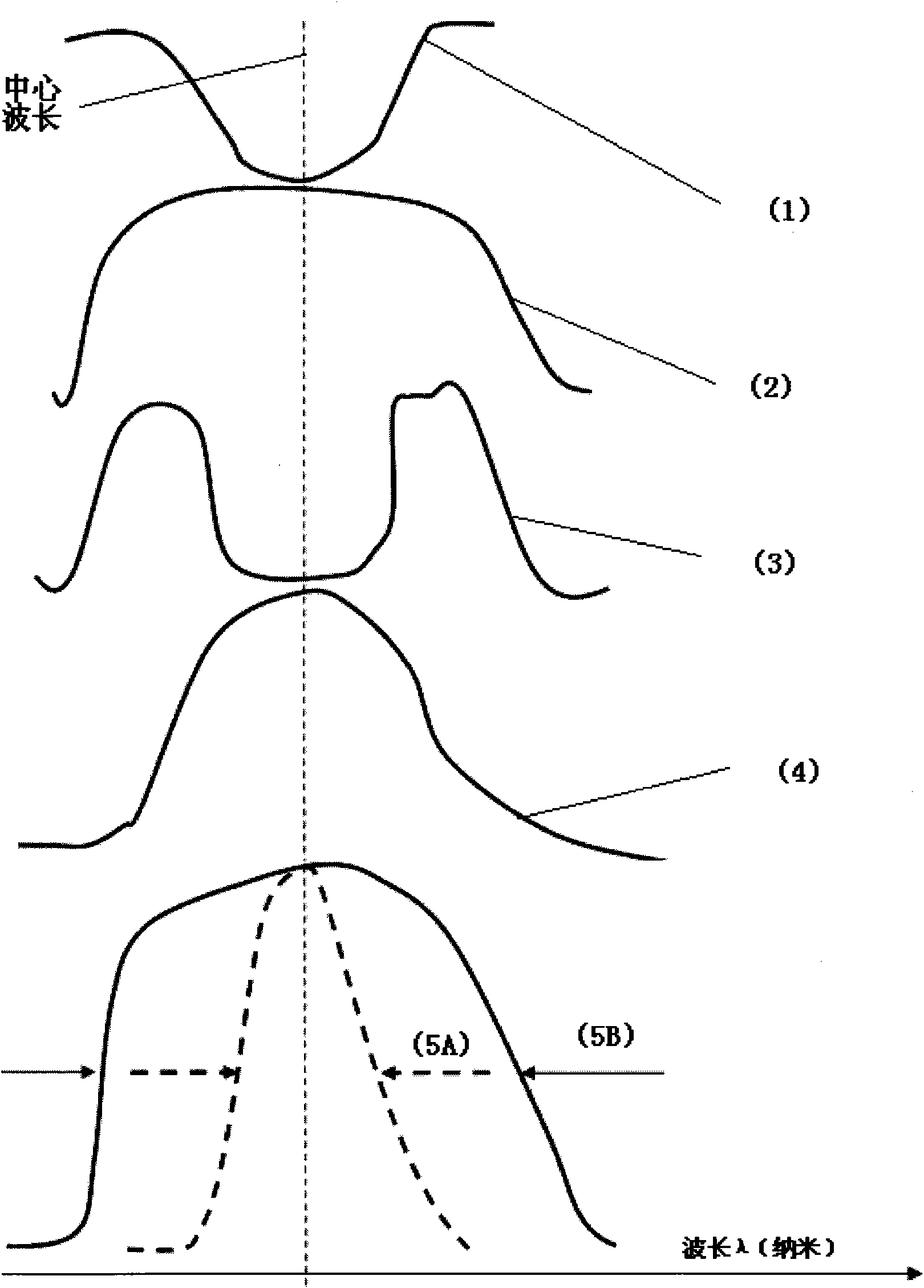
The gain-narrowing effect reported today in high-power ultrashort-pulse fiber laser amplifiers has not yet had a good solution [Tino Eidam, Steffen H¨adrich, Fabian R¨oser, Enrico Seise, Thomas Gottschall, Jan Rothhardt, Thomas Schreiber, Jens Limpert, and Andreas T¨unnermann A325-W-Average-Power Fiber CPA System Delivering Sub-400 fs Pulses, IEEE JOURNAL OF SELECTED TOPICS IN QUANTUM ELECTRONICS, VOL.15, NO.1, JANUARY / FEBRUARY 2009187; F. T. Eidam, J. Rothhardt, O. Schmidt, D.N. Schimpf, J. Limpert, and A. Tünnermann, Millijoule pulse energy high repetition rate femtosecond fiber chirped-pulse amplification system, December 15, 2007 / Vol.32, No.24 / OPTICS LETTERS 3495; Jens Limpert, Fabian R¨oser, Damian N. Schimpf, Enrico Seise, Tino Eidam, Steffen H¨adrich, Jan Rothhardt, C′esar Jauregui Misas, and Andreas T¨unnermann, High Repetition Rate Gigawatt Peak Power Fiber LaserSystems: Challenges , Design, and Experiment, IEEE JOURNAL OF SELECTEDTOPICS IN QUANTUM ELECTRONICS, VOL.15, NO.1, JANUARY / FEBRUARY, 2009, 159]

Method used


Image

  • Optical fiber chirped pulse amplifier for ultra-short laser pulse output
  • Optical fiber chirped pulse amplifier for ultra-short laser pulse output
  • Optical fiber chirped pulse amplifier for ultra-short laser pulse output

Examples


Embodiment 1

[0073] This embodiment provides a single-stage ultrashort laser pulse doped with Y b 3+ Structure of a fiber chirped pulse amplifier. A long-period fiber grating spectral filter with concave attenuation is used as the spectral shaping element of the seed laser pulse of the fiber amplifier.

[0074] Its structure is:

[0075] A mode-locked femtosecond laser (such as a mode-locked solid-state laser or a mode-locked fiber laser) is used as a seed laser source for a high-power chirped pulse fiber amplifier. The spectral bandwidth of the seed laser source is 40 nm (full width at half maximum), and the center wavelength The output laser pulse width is 1040 nanometers, the output laser pulse width is 80 femtoseconds, the repetition rate of the optical pulse is 30MHz, and the single pulse energy is 0.2 nanojoules; the seed laser pulse passes through an optical pulse stretcher (such as optical fiber or grating, etc.) and an optical pulse selector Finally, the width of the optical pu...

Embodiment 2

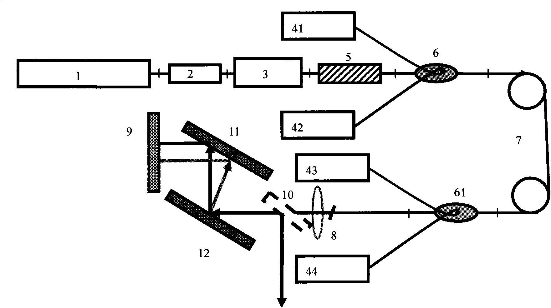
[0100] This embodiment provides a high repetition rate, high power, ultrashort laser pulse doped Y b 3+ The structure of the fiber chirped pulse single-stage amplifier uses a concave attenuation long-period fiber grating spectral filter as the spectral shaping element of the seed laser pulse of the fiber amplifier, which overcomes the high-power Y-doped b 3+ Gain Spectrum Narrowing Effect in the Amplification Process of Fiber Chirped Pulse Amplifier, Realizing All-Fiber High Power, Ultrashort Laser Pulse Doped with Y b 3+ Optical Fiber Chirped Pulse Amplification.

[0101] See attached figure 2 , it is a single-stage high-power Y-doped Y-doped spectral filter that uses a concave attenuation long-period fiber grating spectral filter as the spectral shaping element of the seed laser pulse of the fiber amplifier provided by this embodiment b 3+ Schematic diagram of the structure of a fiber chirped pulse amplifier. The mode-locked femtosecond seed laser pulse passes throug...

Embodiment 3

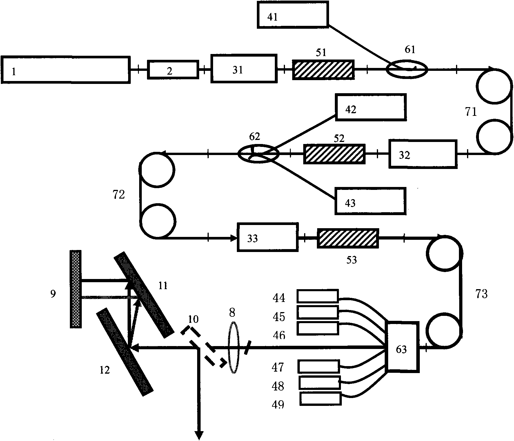
[0103] Embodiment 3: This embodiment provides a three-stage ultrashort laser pulse doped with Y b 3+ The structure of the fiber chirped pulse amplifier uses a three-stage concave attenuation long-period fiber grating spectral filter with different structures as the seed laser pulse of the fiber amplifier and the spectral shaping element of the optical pulse before each subsequent amplifier, which overcomes the high-power doping Y b 3+ Gain Spectrum Narrowing Effect in Fiber Chirped Pulse Amplification Process to Realize All-Fiber High Power, Ultrashort Laser Pulse Doped with Y b 3+ Optical Fiber Chirped Pulse Amplification.

[0104] See attached image 3 , which is a schematic structural composition diagram of an optical fiber chirped pulse amplifier outputting ultrashort laser pulses provided in this embodiment. Depend on image 3 It can be seen that the specific connection relationship is: the femtosecond laser pulse output by the mode-locked laser [1] enters the optica...


PUM


Abstract

The invention discloses an optical fiber chirped pulse amplifier for ultra-short laser pulse output, which has the advantages of high pulse repetition rate, high power and ultra-short laser pulse output and belongs to the technical field of optical information. The optical fiber chirped pulse amplifier adopts an optical fiber type concave attenuating long-period fiber grating as a seed laser pulse of a high-power chirped femtosecond laser pulse amplifier or a spectral shaping component of a laser pulse amplified by a preamplifier, thereby eliminating the gain spectrum narrowing effect caused during amplification of the high-power chirped femtosecond laser pulse optical-fiber amplifier, increasing the spectral bandwidth of the amplified laser pulse. The laser pulse with smaller pulse width and higher peak power can be obtained through compression. The high-power chirped femtosecond laser pulse amplifier which has the advantages of high repetition rate, high power, simple structure and high efficiency and can be fully made of optical fiber is applicable to such industrial fields as precision machining, precision lithography, laser fusion and the like of semiconductor devices and metal materials and the basic scientific research such as biomedical imaging.

Description

technical field [0001] The invention relates to an optical fiber amplifier, in particular to an optical fiber chirped pulse amplifier with high pulse repetition rate, high power, and ultrashort laser pulse output, which is suitable for industrial fields such as semiconductor devices, metal material precision processing, and precision lithography. Life science technologies such as biomedical imaging, precision dental and eye surgery, and basic scientific research fields for ultrafast optical science experiments, strong field science and technology experiments, and laser nuclear fusion belong to the field of optical information technology. Background technique [0002] In recent years, due to the rapid development of femtosecond laser chirped pulse amplification technology [Chirped Pulses Amplification, CPA] and the continuous emergence of high-quality laser media with broadband gain, the peak power of ultrashort laser pulses on the table has increased by 6-7 in just a few year...

Claims


Application Information

Patent Timeline
IPC IPC(8): G02F1/39G02F1/365G02B6/02
Inventor 刘东峰王钦华余建军朱晓军
Owner SUZHOU UNIV
Learn More