Plastic and metal permanent direct connection method

A permanent, welding connection technology, applied in the field of metal and plastic welding, can solve the problems of increasing the connection cost of components, consuming man-hours, reducing connection efficiency, etc. Effect

Inactive Publication Date: 2017-01-04
WUHAN LINGYUN PHOTOELECTRONICS SYST
View PDF8 Cites 17 Cited by
  • Summary
  • Abstract
  • Description
  • Claims
  • Application Information

AI Technical Summary

Problems solved by technology

This method has to process metal parts in advance, and metal processing is time-consuming, resulting in a significant reduction in the efficiency of the entire connection and a significant increase in cost, which is not conducive to popularization and application
[0004] The riveting technology patent number is "CN201610167498", which is a Chinese invention patent named "An Ultrasonic Metal Riveting Method for Good Connection between Plastic and Metal". Riveting technology usually requires processing pin structures on metal parts and processing on plastic parts. Create the corresponding pin hole structure, insert the pin into the pin hole during welding, and then perform melting or other treatment to fix the two together. This way the connection is very tight, but due to the need to process the corresponding structural parts in advance , which also increases the man-hours of parts processing and increases the cost of parts connection, which is not conducive to popularization and operation
[0005] Another NMT technology with different perspectives is more advanced, such as the US invention patent named "System and method for plastic overmolding on a metal surface" with the patent number "US20110250377". Treatment, corroding the metal surface to form a nano-scale microporous structure, and then injecting plastic components on the metal surface, which is suitable for various thicknesses, not limited to component sizes, but the connection strength is limited and it is difficult to further improve. In addition, this technology uses chemical processes, which is not environmentally friendly. , it is difficult for local processing of components

Method used


Image

  • Plastic and metal permanent direct connection method
  • Plastic and metal permanent direct connection method
  • Plastic and metal permanent direct connection method

Examples


Embodiment Construction

[0034] The present invention will be further described in detail below in conjunction with the accompanying drawings and specific embodiments.

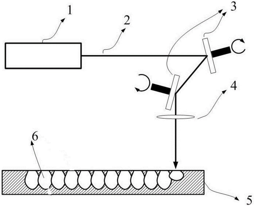
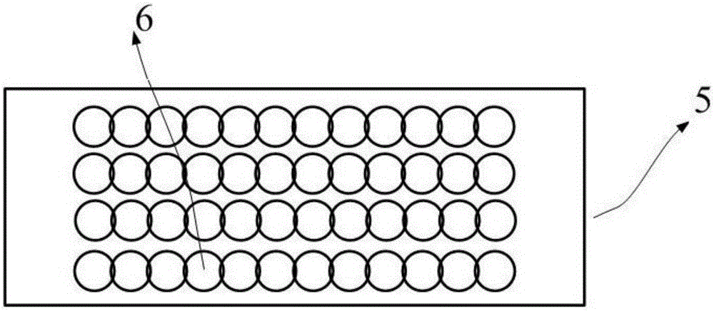
[0035] like Figure 1-6 , the method of welding the metal part and the plastic part in this embodiment is:

[0036] Step 1: If figure 1 As shown, the laser beam 2 that can be processed on the surface of the metal part is emitted by the laser light source 1, the wavelength of the laser beam 2 of the present embodiment is 355nm, the average power is 10W, the pulse width is 20ns, the repetition frequency is 40kHz, and the beam quality factor M2 is 1.5, the laser beam 2 of this embodiment has strong processing capability and can process most metal materials. The laser beam 2 passes through the scanning galvanometer 3 and the scanning lens 4 (the galvanometer is used to change the direction of the laser beam 2, and the lens is used to focus the laser beam 2, and moving the galvanometer and the lens at the same time can make the focused l...


PUM

PropertyMeasurementUnit
wavelengthaaaaaaaaaa
poweraaaaaaaaaa
diameteraaaaaaaaaa

Abstract

The invention relates to the technical field of metal and plastic welding, in particular to a plastic and metal permanent direct connection method. A plurality of connecting holes distributed in a cellular manner are ablated in the surface of a metal component by utilizing laser beams to irradiate at the surface of the metal component. A connecting surface of a plastic component is attached with the surface of the metal component, molten liquid plastic enters the connecting holes, and after the plastic entering the connecting holes is cooled, the welding connection of the metal component and the plastic component is fully realized. The welding method utilizes high-peak power, high beam quality and short-pulse laser beams to treat the metal surface and form the microstructural cellular holes in the surface, micro-hole diameter, depth and filling density can all be flexibly controlled, corresponding adjustment can be carried out according to actual requirements, and the adaptability is better.

Description

technical field [0001] The invention relates to the technical field of metal and plastic welding, in particular to a preparation method for permanent direct connection of plastic and metal. Background technique [0002] With the rapid development of technologies such as automobiles, mobile phones, computers, and home appliances, the requirements for lightweight equipment and components are getting higher and higher. Metal has a lustrous texture and good electrical conductivity, while plastic has the characteristics of low density, light weight and good insulation performance. . Combining plastics with metals is increasingly used in mechanical and electronic manufacturing. In order to achieve the goal of the perfect combination of plastic and metal, various industries have made many attempts and efforts. Representative processes include gluing, electroplating, riveting, metal insert injection molding, and NMT technology. Adhesive technology has limited strength and cannot g...

Claims


Application Information

Patent Timeline
Patent Type & Authority Applications(China)
IPC IPC(8): B29C65/16B29C65/44
CPCB29C66/30325B29C65/1616B29C65/1629B29C65/1635B29C65/44B29C66/0246B29C66/1122B29C66/342B29C66/472B29C66/742B29C66/8122B29C66/81267B29C66/8322B29K2909/08B29C65/1632
Inventor 刘良清
Owner WUHAN LINGYUN PHOTOELECTRONICS SYST
Why Eureka
Try Eureka