Method of operating an internal combustion engine

a technology of internal combustion engine and combustion chamber, which is applied in the direction of machines/engines, output power, electric control, etc., can solve the problems of difficult selective control of combustion described, adversely affecting operation, and higher manufacturing costs of such internal combustion engine, so as to reduce the reactivity of the total cylinder charge, increase the mixture reactivity, and reduce the effect of high burning speed

Active Publication Date: 2006-12-05
DAIMLER AG
View PDF16 Cites 8 Cited by
  • Summary
  • Abstract
  • Description
  • Claims
  • Application Information

AI Technical Summary

Benefits of technology

[0009]The injection of fuel in the intake manifold leads to better homogenization of the fuel / air mixture which is formed and at the same time reduces the raw emissions of the internal combustion engine. By carrying out the first fuel injection by means of a direct fuel injection the reactivity of the mixture can be more easily and better influenced. As a result, in the method according to the invention the advantages of direct fuel injection and the advantages of port fuel injection are combined in an advantageous way so that the control of the current combustion process can be optimized. The first injector is preferably configured and optimized for direct fuel injection of small fuel quantities so that the installation space which is required for the first injector in the combustion chamber or in the cylinder head can be minimized. As a result, the position of the injector and the injection angle can easily be adapted to the requirements. In this context, the second injector in the inlet port can be configured and optimized for relatively large fuel quantities in order to be able to carry out full load operation of a spark ignition engine if necessary.
[0011]The injection of the first fuel quantity into the retained exhaust gas brings about optimum homogenization or preconditioning of the first fuel quantity, which leads to an increase in mixture reactivity of the fuel / air mixture which is formed from the first and second fuel quantities. This favors the inception of the auto-ignition, in particular at operating points with a low exhaust gas temperature. The first fuel injection is preferably performed between the closing of an outlet valve and the opening of an inlet valve. Depending on the injection time of the first fuel quantity, the preconditioning effect can extend beyond pure homogenization. If, in particular, the fuel is injected into the retained exhaust gas before the top dead center of the charge change, if the exhaust gas also contains residual air, conversion-like reactions can occur, as a result of which the temperature of the mixture can be influenced, in particular increased.
[0013]According to a further refinement of the invention, a center of the combustion activity is established by injecting a third fuel quantity after the injection of the second fuel quantity has ended and preferably before a top dead center position of the piston. The third fuel quantity is aimed at reducing the reactivity of the total cylinder charge in particular under high loads. This is intended to reduce high burning speeds and large pressure peaks in the combustion chamber.

Problems solved by technology

During full load operation, a stoichiometric mixture is frequently formed and spark-ignited because at high loads steep rises in pressure could occur in the combustion chamber due to the auto-ignition and these would adversely affect the operation.
In accordance with the current state of the art however, it is difficult to selectively control the combustion described above since the time of auto-ignition depends very greatly on the parameters of the engine and the ambient conditions.
Such concepts are, however, associated with a high degree of expenditure on engine control technology which results in higher manufacturing costs of such internal combustion engines.

Method used


Image

  • Method of operating an internal combustion engine
  • Method of operating an internal combustion engine
  • Method of operating an internal combustion engine

Examples


Embodiment Construction

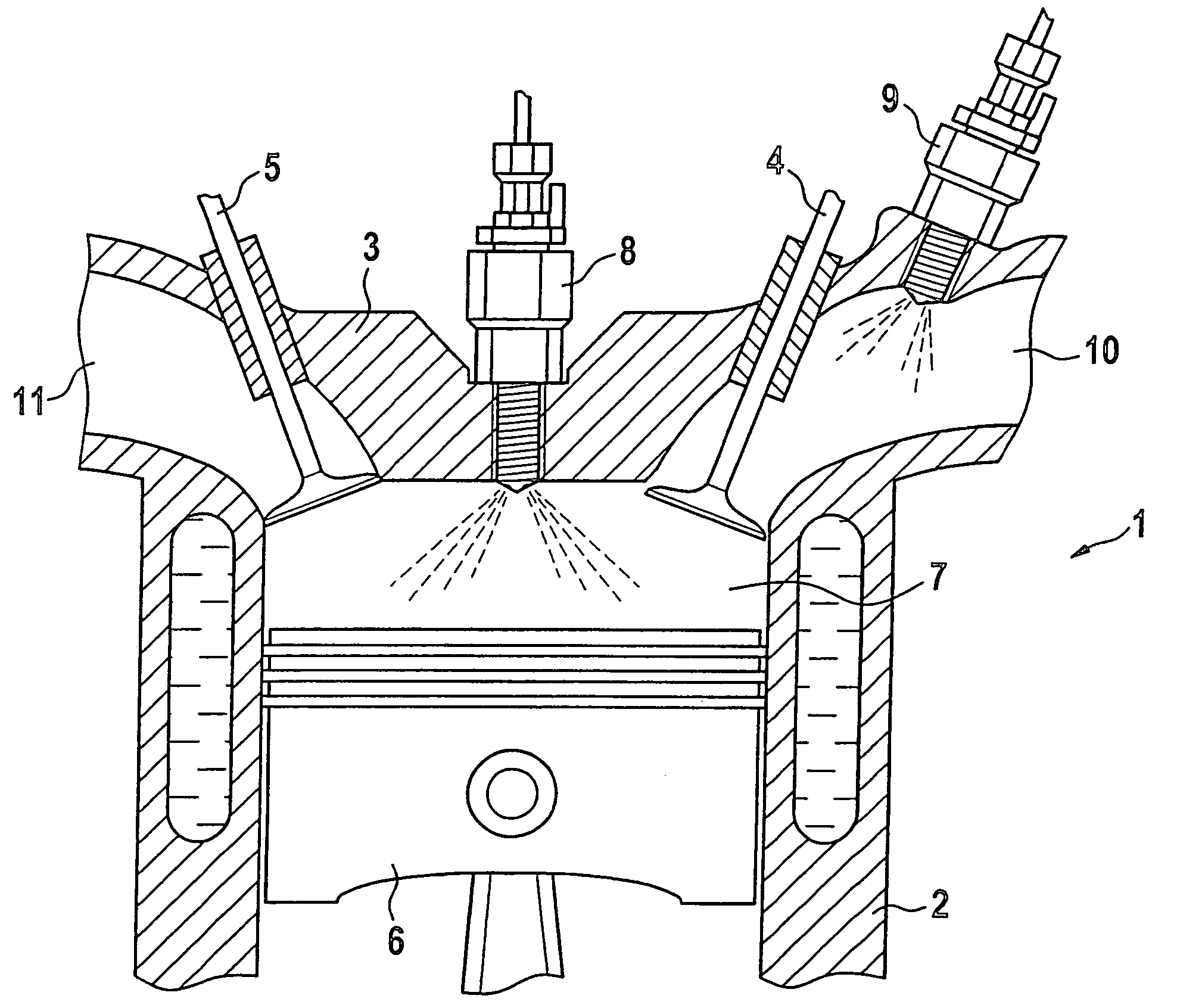
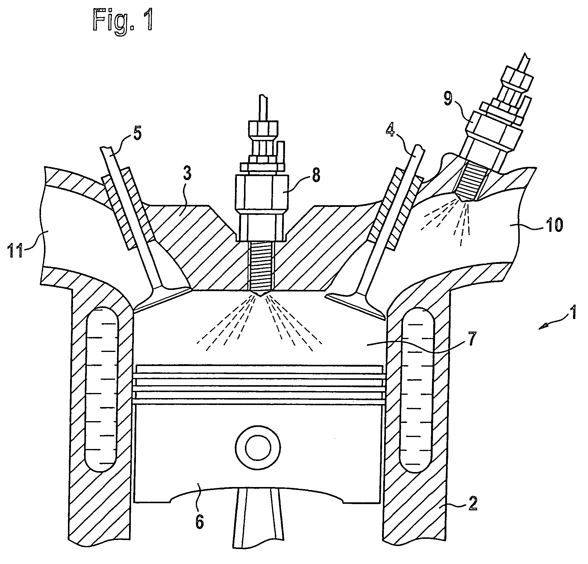
[0018]FIG. 1 illustrates a cylinder of an internal combustion engine 1 with direct and port fuel injection in which a combustion chamber 7 is formed in at least one cylinder 2 between a piston 6 which is movable longitudinally in the cylinder 2 and a cylinder head 3. The internal combustion engine 1 comprises, per combustion chamber 7, at least one inlet valve 4, at least one outlet valve 5, a first fuel injector 8, a second fuel injector 9 and an ignition source (not illustrated) which is preferably embodied as a spark plug. Furthermore, an inlet port 10 and an outlet port 11 with inlet and outlet valves are arranged in the cylinder head 3. The number of inlet and outlet valves is exemplary and can be increased as necessary.

[0019]The first fuel injector 8 is provided for direct fuel injection into the combustion chamber 7 and therefore projects into the combustion chamber 7. The second fuel injector 9 is arranged in the inlet region and is preferably configured for injecting larger...


PUM


Abstract

In a method of operating an internal combustion engine in which exhaust gas is retained in the combustion chamber of the internal combustion engine and compressed during a charge change together with fresh combustion air, a first fuel quantity is injected into the retained exhaust gas by means of direct fuel injection, a second fuel quantity is subsequently supplied to the combustion chamber together with the fresh combustion air so that a homogeneous fuel / gas / air mixture is formed in the combustion chamber, and an auto-ignition time of the fuel / gas / air mixture is established as a function of a quantity ratio of the first fuel quantity and the second fuel quantity.

Description

[0001]This is a Continuation-In-Part Application of International Application PCT / EP2004 / 011372 filed 12 Oct. 2004 and claiming the priority of German Application 103 50 797.3 filed 29 Oct. 2003.BACKGROUND OF THE INVENTION[0002]The invention relates to a method of operating an internal combustion engine, in particular a compression- or auto-ignition internal combustion engine with direct fuel injection including a cylinder with a cylinder head having intake and exhaust valves and a piston for compressing combustion gases in the cylinder into which fuel is injected for combustion therein.[0003]In direct-injection internal combustion engines with auto-ignition, lean homogeneous fuel / air mixtures are often made to auto-ignite so that high efficiency levels and improved exhaust emissions are obtained. In such internal combustion engines which are referred to as HCCI or PCCI internal combustion engines, that is, internal combustion engines with spatial compression ignition, a lean basic ...

Claims


Application Information

Patent Timeline
Patent Type & Authority Patents(United States)
IPC IPC(8): F02B3/08F02B17/00F02B23/08F02B23/10F02B75/02F02B75/12F02D13/02F02D41/30F02M25/07
CPCF02B23/08F02B23/104F02D13/0265F02D41/3035F02D41/3047F02D41/3094F02M25/0752F02B17/005F02B2075/027F02B2075/125F02D41/006Y02T10/125Y02T10/128Y02T10/18Y02T10/123F02M26/01Y02T10/12
Inventor BRACHERT, GOTZHERWEG, RUDIGERPFAU, MATTHIASSCHAFLEIN, JOCHENWEIMANN, HANS-JURGEN
Owner DAIMLER AG
Why Eureka
Try Eureka