High temperature line expansion installation with bellows

a pre-insulated piping and high temperature technology, applied in the direction of adjustable joints, sleeves/socket joints, mechanical equipment, etc., can solve the problems of destroying the jacket at the first change of direction, pushing through and destroying the jacket, and putting into question the strength of the foam bond to the steel carrier pip

Inactive Publication Date: 2006-12-05
THERMACOR PROCESS
View PDF17 Cites 23 Cited by
  • Summary
  • Abstract
  • Description
  • Claims
  • Application Information

AI Technical Summary

Benefits of technology

[0014]Another object of the invention is to provide such a flexible coupling which includes a bellows arrangement in combination with other specific materials to provide a flexible coupling which eliminates the tendency of an elbow to pose expansion problems in the presence of high temperatures or pressures.

Problems solved by technology

Higher temperatures can act adversely upon the bonded foam system, however.
If the system however were to disbond, the surrounding soil would fix the jacket in place and the carrier pipe would still thermally expand thereby pushing thorough and destroying the jacket at the first change of direction.
However, in systems utilizing “high temperature” polyiscyanurate foam, the higher heat can, in some instances, begin to fry the foam at the foam / carrier pipe interface, thereby bringing into question the strength of the foam bond to the steel carrier pipe.

Method used


Image

  • High temperature line expansion installation with bellows
  • High temperature line expansion installation with bellows
  • High temperature line expansion installation with bellows

Examples


Embodiment Construction

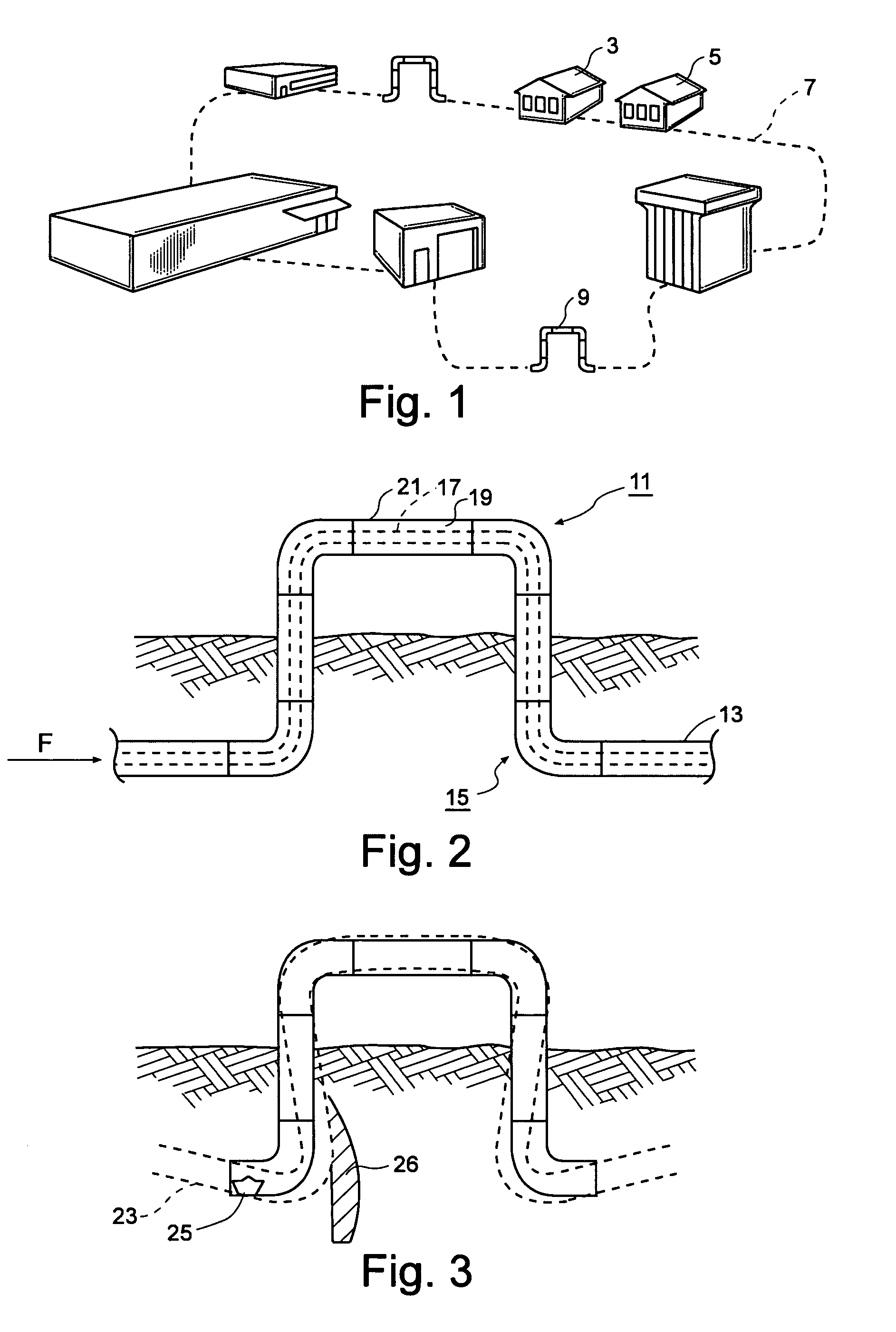
[0026]Turning first to FIGS. 1–3, there is illustrated a typical environment in which the pre-insulated piping systems of the invention might be employed. FIG. 1 shows a school campus having a number of isolated buildings 3, 5 connected by an underground insulated pipeline carrying steam which at points includes right angle loops or elbows 9.

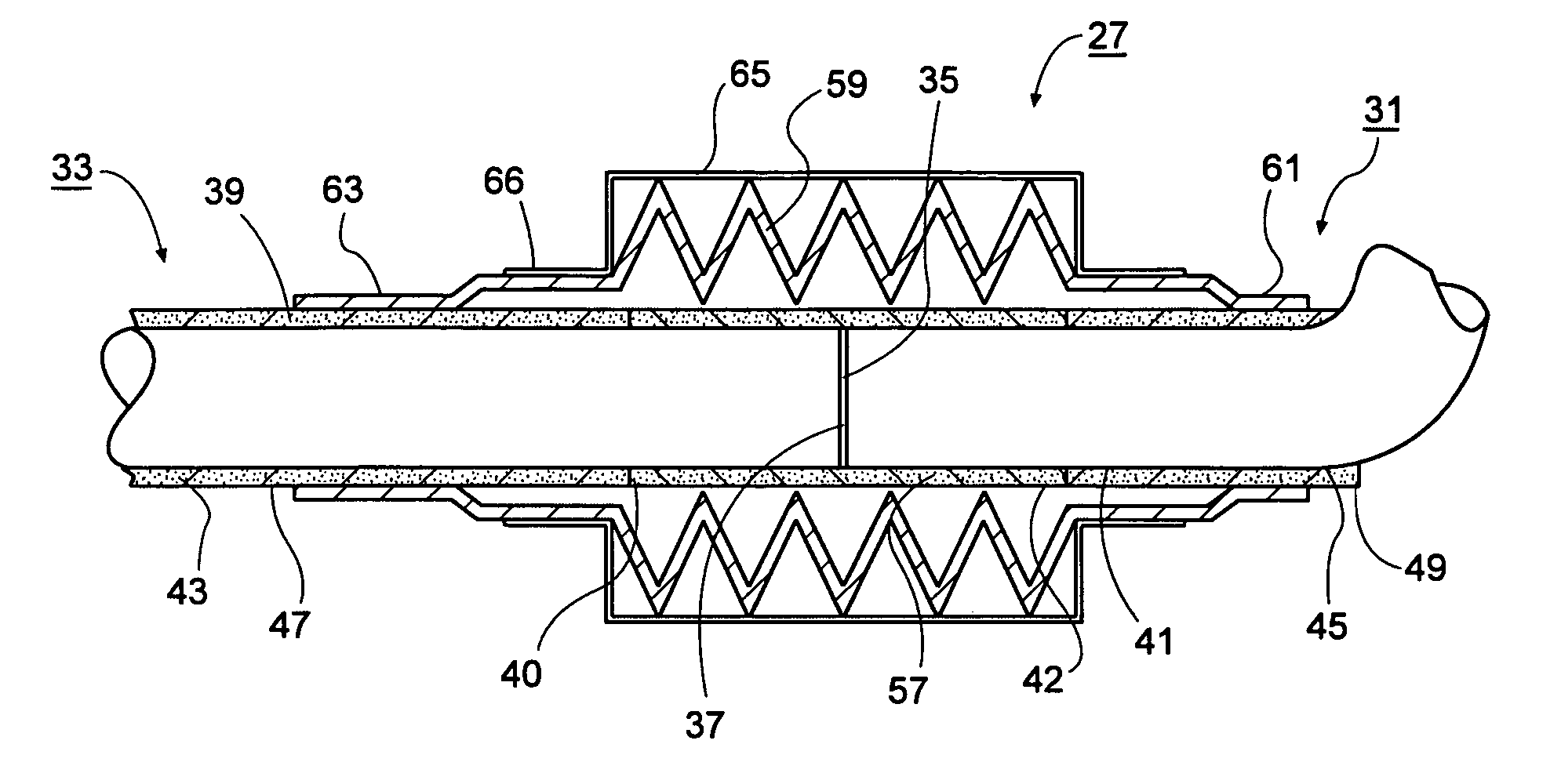
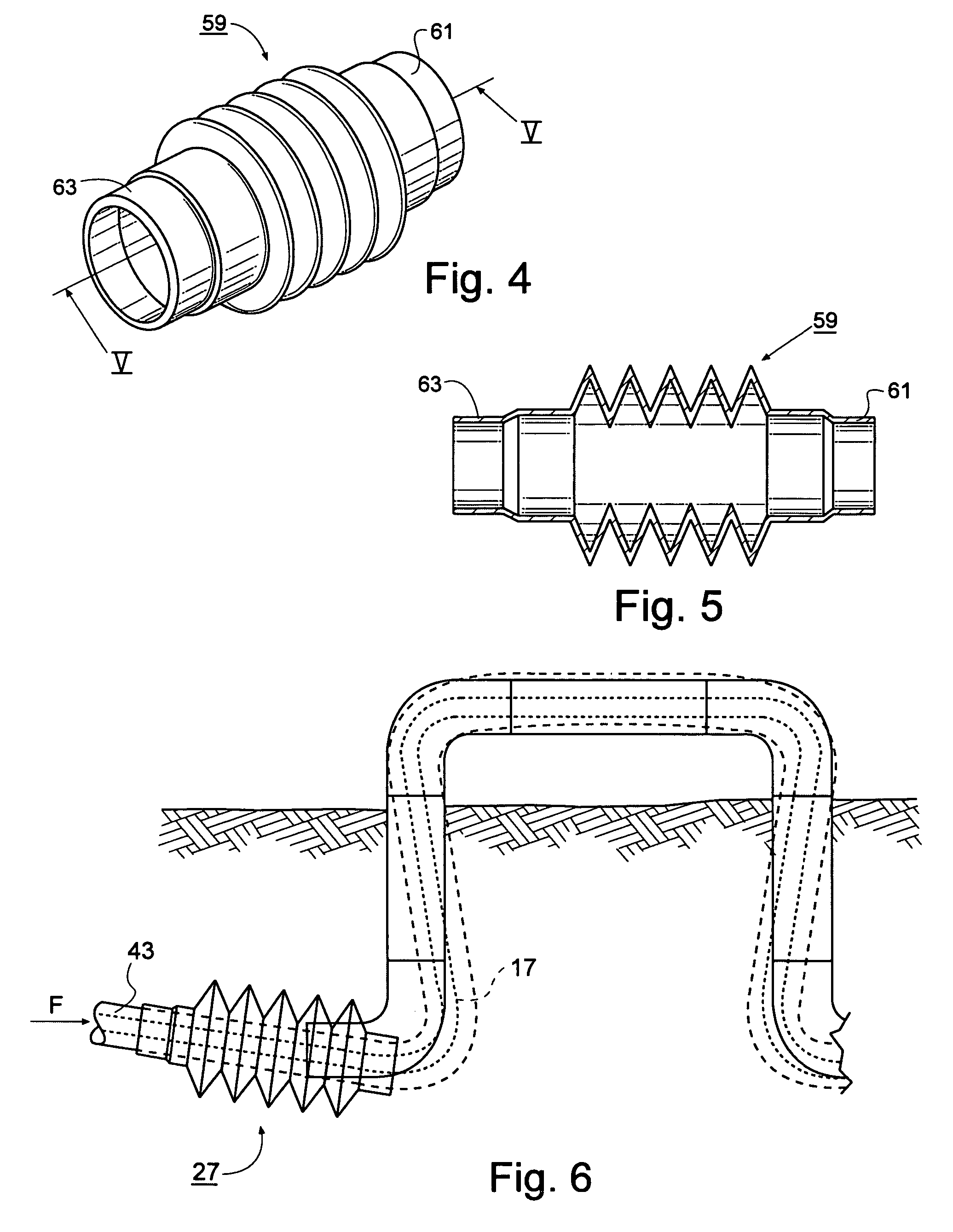
[0027]FIGS. 2 and 3 are schematic views of the standard piping installation of the type under consideration designated generally as 11. The installation 11 includes a number of coaxially oriented lengths of pipe, such as length 13 (shown broken away in FIG. 2). The installation may also include a number of angled fittings such as the right angle elbows (generally shown as 15) in FIG. 2. Each length of pipe includes an inner pipe 17, typically formed of steel, an envelope of foamed insulation 19 surrounding the inner pipe and outer protective jacket 21 surrounding the envelope of insulation. The joining ends (shown generally as 35, 37 in FIG. 7) ...


PUM


Abstract

An flexible coupling is shown for an insulated piping system of the type used to convey steam and other high temperature fluids. The coupling uses a flexible bellows and additional insulating and joining components to couple conventional lengths of insulated pipe. The bellows arrangement compensates for any relative movement of the inner fluid conveying pipes with respect to the outer layers of insulating material and outer jacket in order to protect the integrity of the assembly and prevent the intrusion of water or other contaminants which could lead to corrosion or early failure of the piping system.

Description

BACKGROUND OF THE INVENTION[0001]1. Field of the Invention[0002]The present invention relates to foam bonded pre-insulated piping systems, and more specifically to an expansion installation which compensates for the disbandment of the foam from the carrier pipe as these systems thermally expand in the presence of high temperature fluids being conveyed.[0003]2. Description of the Prior Art[0004]There are many instances in which insulated pipelines are needed. For example, distributed HVAC (heating, ventilation and air conditioning) applications utilize chilled water for cooling and steam for heating. The chiller and boiler are typically contained in a central location and the chilled water and steam are distributed to other locations. For example, on a school campus, the chiller and boiler may be located in a power plant building. The chilled water and steam are distributed to classrooms in separate buildings.[0005]A set of insulated pipelines is used to convey the chilled water from...

Claims


Application Information

Patent Timeline
Patent Type & Authority Patents(United States)
IPC IPC(8): F16L11/00
CPCF16L51/025F16L59/143F16L59/15F16L51/04
Inventor KEYES, THOMAS JOSEPH
Owner THERMACOR PROCESS
Why Eureka
Try Eureka