Heat sink with angled heat pipe

a heat pipe and sink technology, applied in the direction of lighting and heating apparatus, semiconductor/solid-state device details, laminated elements, etc., can solve the problems of inefficiency, complex design of the base-pipe interface, failure to operate the electronic component, etc., to maximize the contact surface area, and heat is dissipated more efficiently

Inactive Publication Date: 2006-12-05
HEWLETT PACKARD DEV CO LP
View PDF41 Cites 19 Cited by
  • Summary
  • Abstract
  • Description
  • Claims
  • Application Information

AI Technical Summary

Benefits of technology

[0008]By providing a heat pipe in a heat sink that is L-shaped or U-shaped, a greater portion of the heat pipe is in contact with the heat-generating electronic component. As a result, heat is dissipated more efficiently compared with indirect contact with the heat pipe. The heat pipe may be of any shape wherein two different regions are in two different planes, one plane being the plane of the substantially flat region of the base. In this regard, a heat pipe can be designed to maximize the contact surface area of the heat pipe with the heat-generating component to dissipate heat.

Problems solved by technology

As the generated heat increases above a critical temperature, a failure can occur in the operation of the electronic component.
Furthermore, sometimes the bases of these heat pipes are rectangular and the heat pipe itself is round so the base-pipe interface may have a complex design.
This, however, is less efficient due to the added thermal resistance of the base and the material (e.g. adhesive) used to attach the heat pipe to the base.
Yet another problem with a heat pipe is that it can fail by forming a leak such that the vacuum pressure decreases, possibly by corrosion of the wicking material, contamination of the fluid, etc.
As a result, when a heat pipe fails, it becomes less effective at transferring heat from the electronic component to the ambient environment and thus becomes less effective in cooling the component.
If the failure of the heat pipe is severe enough, the component can overheat and fail.

Method used


Image

  • Heat sink with angled heat pipe
  • Heat sink with angled heat pipe
  • Heat sink with angled heat pipe

Examples


Embodiment Construction

[0015]The following discussion is presented to enable one skilled in the art to make and use the invention. Various modifications to the disclosed embodiments will be readily apparent to those skilled in the art, and the generic principles herein may be applied to other embodiments and applications without departing from the spirit and scope of the present invention as defined by the listed claims. Thus, the present invention is not intended to be limited to the embodiments shown, but is to be accorded the widest scope consistent with the principles and features disclosed herein.

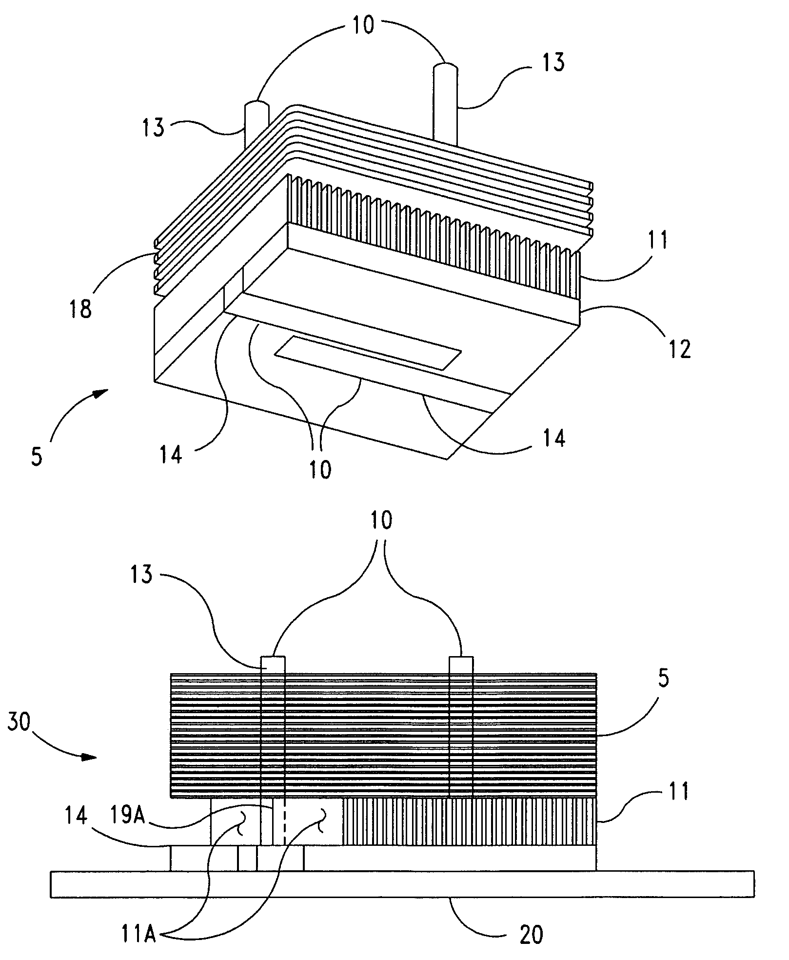
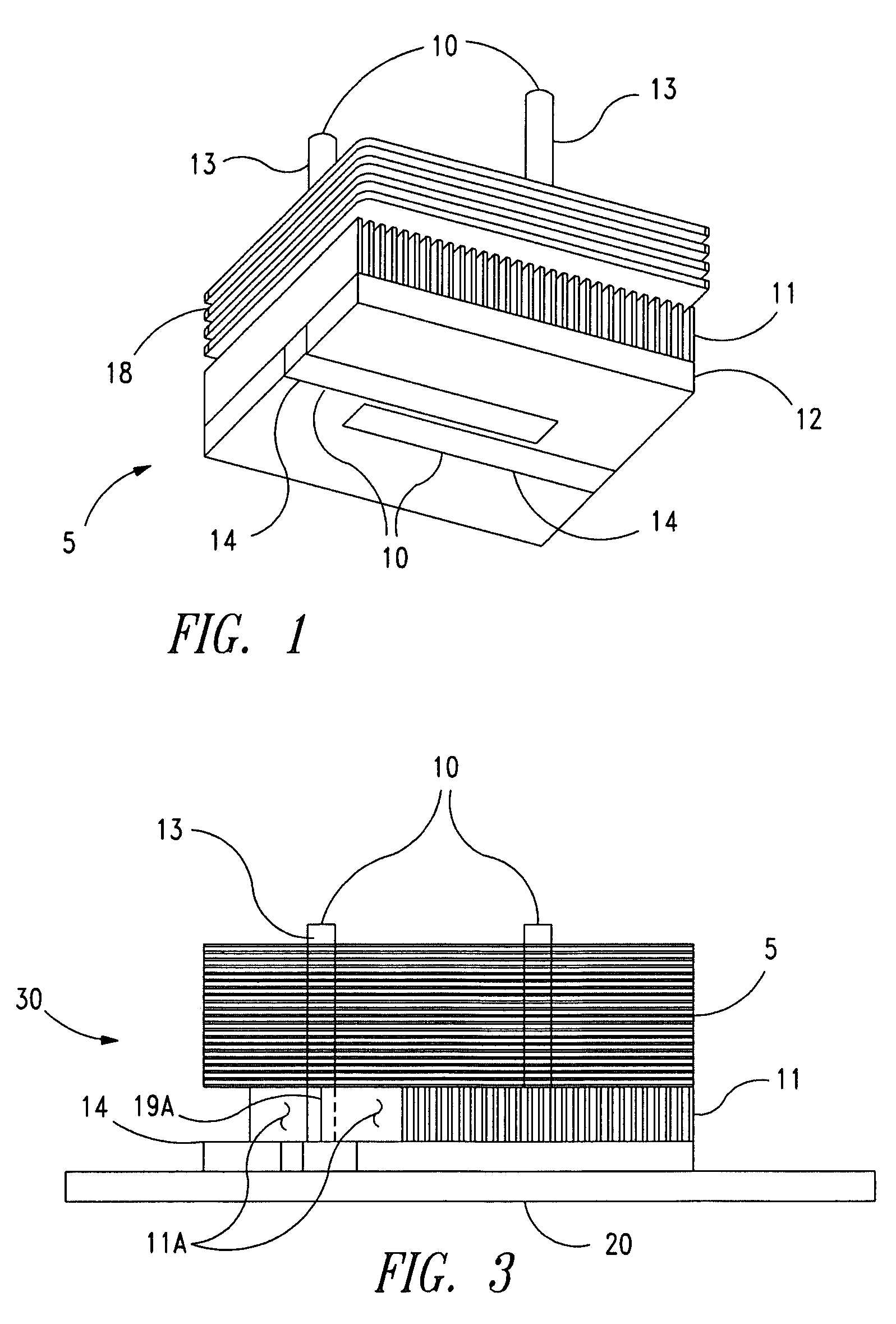
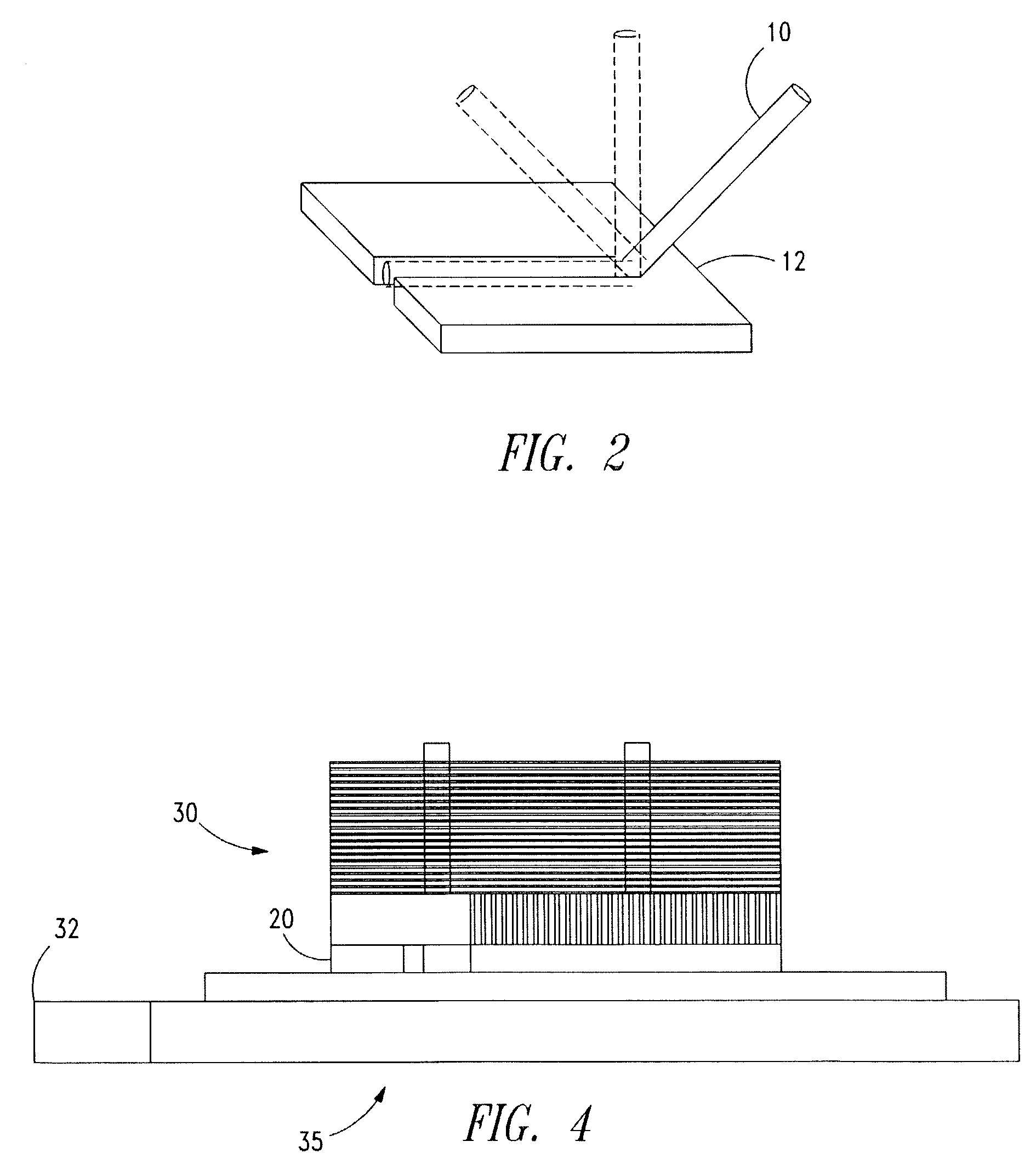
[0016]FIG. 1 is an isometric view of a heat sink 5 according to an embodiment of the invention. The heat sink 5 comprises multiple heat pipes although alternative embodiments only include one heat pipe. According to this embodiment, there are two heat pipes 10 attached to a base 12. A heat pipe 10 is attached to the base 12 in any conventional manner, including adhesive, form-fitted (“snap-on”), harnessed, b...


PUM


Abstract

A heat sink comprises a base having a substantially flat region for interfacing with an electronic component, and at least one heat pipe having a first region substantially parallel to the flat region of the base and a second region substantially perpendicular to the flat region of the base. By providing a heat pipe in a heat sink that is L-shaped or U-shaped, a greater portion of the heat pipe is in contact with the heat-generating electronic component. As a result, thermal efficiency increases because there is more direct contact with the heat pipe.

Description

CROSS-RELATED APPLICATIONS[0001]This application is related to utility patent applications U.S. application Ser. No. 10 / 246,343 titled HEAT SINK WITH HEAT PIPE IN DIRECT CONTACT WITH COMPONENT, and U.S. application Ser. No. 10 / 246,322 titled HEAT SINK WITH HEAT PIPE AND BASE FINS, which were filed on the same day as this application and which are hereby incorporated by reference in their entirety.BACKGROUND OF THE INVENTION[0002]It is well known that an electronic component generates heat as it operates. As the generated heat increases above a critical temperature, a failure can occur in the operation of the electronic component. Therefore, the excess heat must be dissipated to prevent such failures.[0003]One type of heat sink used to dissipate heat includes a heat pipe. A heat pipe is a vacuum-sealed pipe that is filled with a heat-transfer liquid, such as water, and has the interior wall of the heat pipe covered with a wicking material. As the electronic component heats up, the “h...

Claims


Application Information

Patent Timeline
Patent Type & Authority Patents(United States)
IPC IPC(8): H05K7/20F28F3/04F28D15/02H01L23/427
CPCH01L23/427F28D15/0275H01L2924/3011H01L2924/0002H01L2924/00
Inventor MALONE, CHRISTOPHER G.MIYAMURA, HAROLD
Owner HEWLETT PACKARD DEV CO LP
Why Eureka
Try Eureka