Detection and handling of semiconductor wafers and wafers-like objects

a technology of semiconductor wafers and waferlike objects, applied in the field of semiconductor wafer processing, can solve the problems of ineffective support of flexible and/or deformed wafers by conventional end-effectors, ineffective end-effectors that support a wafer from the bottom by gravity, and ineffective end-effectors that support a deformed wafer

Inactive Publication Date: 2006-12-05
INVENSAS CORP
View PDF88 Cites 17 Cited by
  • Summary
  • Abstract
  • Description
  • Claims
  • Application Information

AI Technical Summary

Benefits of technology

[0013]In one embodiment, the end-effector has an outline which follows that of the center cut-out portion of a conventional wafer cassette to increase the area of the end-effector for supporting a wafer.
[0014]In one embodiment, the end-effector has a detector for detecting the presence of a wafer. The detector is mounted at a shallow angle to allow the end-effector to be positioned close to a wafer to be picked-up, thereby allowing detection of deformed wafers contained in a wafer cassette. The shallow angle of the detector also minimizes the thickness of the end-effector.
[0016]In one embodiment, the top surface of the wafer station is very flat and has a very smooth finish so that a wafer that is curled down can be picked-up from the station without damaging the edges of the wafer as the wafer curls up during the pick-up step.

Problems solved by technology

Conventional end-effectors are ineffective in supporting flexible and / or deformed wafers.
For example, end-effectors employing vacuum suction do not adequately support a deformed wafer because vacuum sealing requires a relatively flat surface.
End-effectors that support a wafer from the bottom by gravity are also ineffective because deformed wafers have unpredictable shapes, and thus cannot provide an end-effector a consistent bottom surface contact area.
End-effectors utilizing the Bernoulli principle are likewise inadequate to support wafers that are not relatively flat.
While the end-effector in the aforementioned PCT application is generally more effective in handling flexible wafers than current non-vortex designs, that end-effector does not have, at least, an effective means for detecting and supporting very thin, flexible wafers.

Method used


Image

  • Detection and handling of semiconductor wafers and wafers-like objects
  • Detection and handling of semiconductor wafers and wafers-like objects
  • Detection and handling of semiconductor wafers and wafers-like objects

Examples


Embodiment Construction

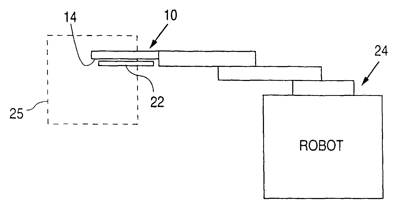
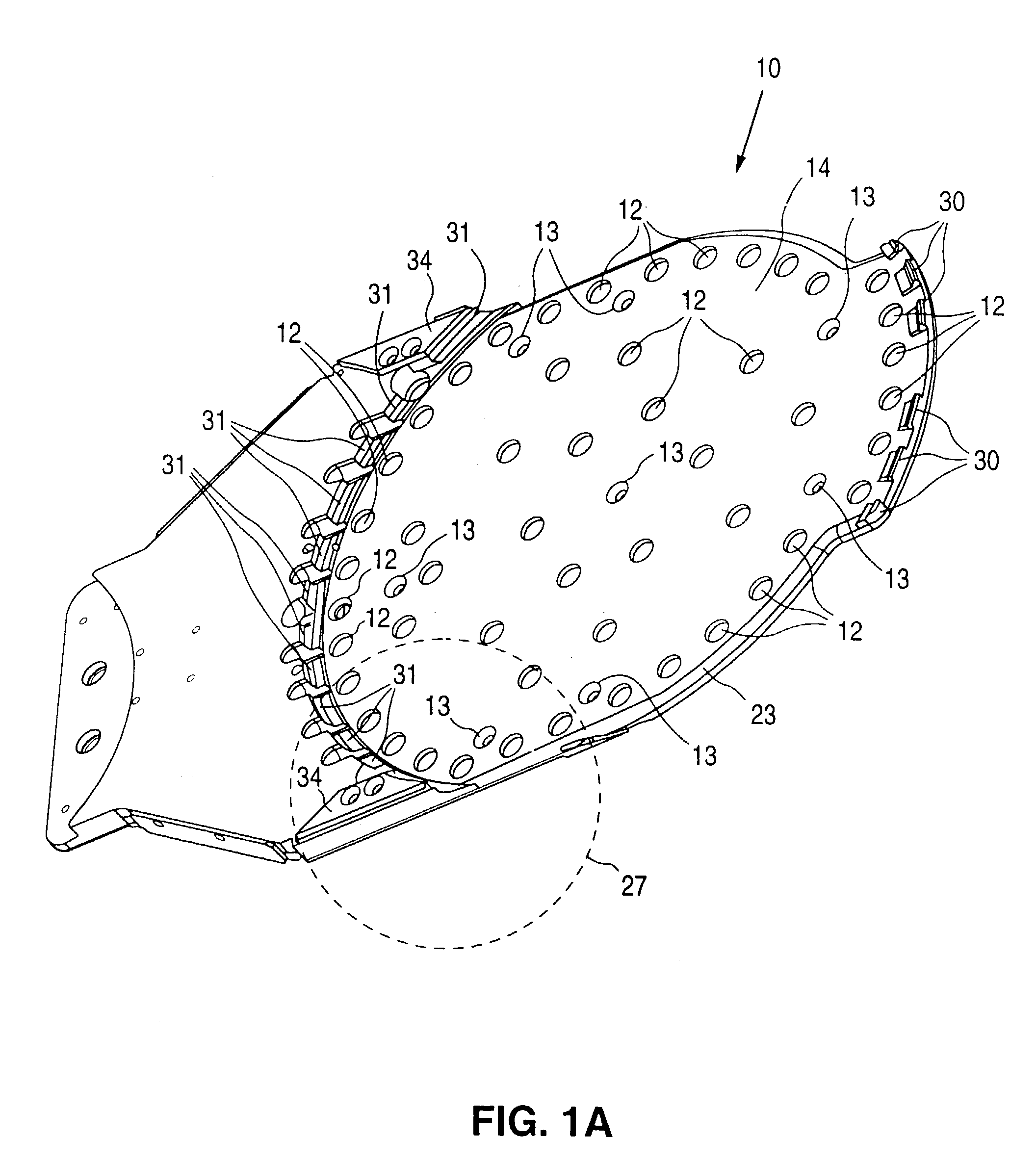
[0032]FIG. 1A shows a three-dimensional view of an end-effector 10 in accordance with an embodiment of the invention. In a typical application, end-effector 10 is attached to an arm of a conventional robot for picking-up and placing semiconductor wafers in a semiconductor manufacturing equipment. In one example, end-effector 10 is utilized in the TRU-ETCH 2000 / 3000™ wafer processing system from Tru-Si Technologies, Inc. of Sunnyvale, Calif. Of course, the invention is not so limited and can be generally used for transporting semiconductor wafers and wafer-like objects.

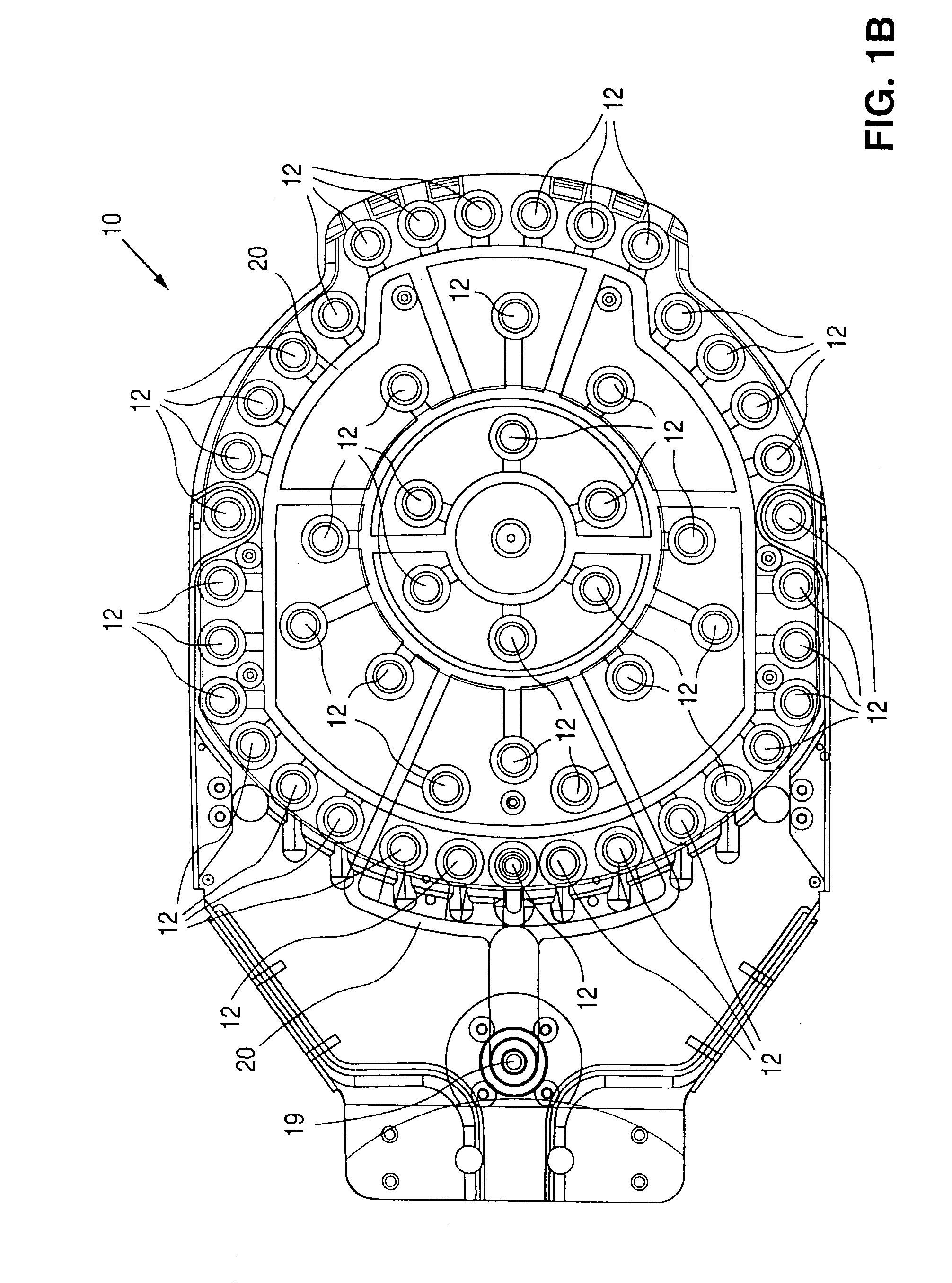
[0033]Referring to FIG. 1A, end-effector 10 includes multiple vortex chucks 12 for supporting a semiconductor wafer. Only some vortex chucks 12 are labeled in FIG. 1A for clarity. Vortex chucks are also described in the following documents: PCT Application WO 97 / 45862; European Patent Application EP 0 807 964 A1; U.S. patent application Ser. No. 09 / 038,642, “HOLDERS SUITABLE TO HOLD ARTICLES DURING PROCESSING, AND ARTI...


PUM


Abstract

An end-effector includes multiple vortex chucks for supporting a wafer. Vortex chucks are located along the periphery of the end-effector to help prevent a flexible wafer from curling. The end-effector has limiters to restrict the lateral movement of a supported wafer. In one example, the end-effector has a detector for detecting the presence of a wafer. The detector is mounted at a shallow angle to allow the end-effector to be positioned close to a wafer to be picked-up, thereby allowing detection of deformed wafers contained in a wafer cassette. The shallow angle of the detector also minimizes the thickness of the end-effector. Also disclosed is a wafer station with features similar to that of the end-effector.

Description

CROSS REFERENCE TO RELATED APPLICATIONS[0001]The present application is a division of U.S. patent application Ser. No. 10 / 116,462 filed Apr. 2, 2002 now U.S. Pat. No 6,688,622 incorporated herein by reference, which is a division of U.S. patent application Ser. No. 09 / 632,236 filed Aug. 4, 2000 now U.S. Pat. No. 6,631,935 incorporated herein by reference.BACKGROUND OF THE INVENTION[0002]1. Field of the Invention[0003]The present invention generally relates to semiconductor wafer processing, and more particularly to methods and associated apparatus for handling semiconductor wafers and wafer-like objects.[0004]2. Description of the Related Art[0005]In a semiconductor wafer processing system, semiconductor wafers are transferred from one station to another using a manipulator such as a robot. A typical robot used in the semiconductor industry has a body, an arm, and an end-effector attached to the arm. The end-effector is the part of the robot that supports a wafer.[0006]Conventional ...

Claims


Application Information

Patent Timeline
Patent Type & Authority Patents(United States)
IPC IPC(8): B25J15/06B25J19/02H01L21/00H01L21/683
CPCH01L21/67259H01L21/6838Y10S414/141Y10S294/907
Inventor CASAROTTI, SEAN A.BERGER, ALEXANDER J.KRETZ, FRANK E.
Owner INVENSAS CORP
Why Eureka
Try Eureka