Cabled massive security barrier

a security barrier and massive technology, applied in roadway safety arrangements, roads, construction, etc., can solve the problems of not being able to support the high tensile force required, not being portable enough to facilitate relocation, and affecting the safety of people and property, etc., to achieve the effect of convenient transportation, low manufacturing cost, and low cost of manufactur

Active Publication Date: 2006-12-05
KONTEK INDS
View PDF33 Cites 26 Cited by
  • Summary
  • Abstract
  • Description
  • Claims
  • Application Information

AI Technical Summary

Benefits of technology

[0028]Objects and advantages of the present invention are cabled massive security barriers (or “barrier walls”) that include heavy masses of composite material arranged longitudinally along the ground or other supporting surface, each mass having longitudinally opposite ends and one or more tunnels running between the opposite ends, and tension cable routed through the tunnels and anchored at least to end-masses using any of a variety of means for anchoring cable. One of the objects and advantages of the present invention is that it uses means for anchoring cable that anchor the cable (or cables) to various members of the masses without requiring an anchor to the ground. Such a barrier wall can be durable to vehicle collisions, durable to explosive blasts, energy absorbing, portable, inexpensive to manufacture, inexpensive to deploy, inexpensive to relocate, and inexpensive to remove. Through the use of tension cable arranged to comprise a suitable cable system, rotational forces applied externally to one mass can be transferred into tension forces along the tension cable and into rotational forces on adjacent masses, lateral forces applied externally to one or more masses can be converted to tension forces along the tension cable, and tension forces along the tension cable can result in compressive forces on the masses. The individual masses are resistant to sliding by virtue of their weight and coefficient of friction with the ground (or other supporting surface). With only longitudinal tension forces in the tension cables through tunnels within the masses, it is an object and advantage of the invention that adjacent masses can be slightly offset from one another either or both horizontally or vertically. By virtue of there being no requirement for anchoring the masses or cable to the ground, the cabled massive security barriers of the present invention are n

Problems solved by technology

Security zones for protecting sensitive groups of people and facilities, be they private, public, diplomatic, military, or other, can be dangerous environments for people and property if threatened by acts of terrorism.
But none of these ground-anchored barriers are portable for ease of relocation.
Massive barriers of concrete made in segments have traditionally not been strongly coupled together and therefore cannot support high enough tensile forces required to keep a wall from opening up under the force of a straight-on vehicle collision.
But none of these references include or suggest using a longitudinal cable system running through tunnels within barrier masses aligned longitudinally.
And none include or suggest a way

Method used


Image

  • Cabled massive security barrier
  • Cabled massive security barrier
  • Cabled massive security barrier

Examples


second embodiment

[0057]FIG. 3A shows a perspective view of a cabled massive security barrier 69, also referred to as a barrier wall 71. The barrier wall 71 includes three masses of composite material 21A′, 21B′, and 21C′ of the second embodiment that are aligned end-to-end longitudinally in a row in forming the barrier wall 71. The two masses of composite material at the opposite ends 81 of the barrier wall 71 comprise a first end-location mass 83 and a second end-location mass 85. A first means for anchoring cable 97 is shown anchoring cable to the left-most end region 47 of the barrier wall 71, at the left-most end of the first end-location mass 83. This first means for anchoring cable 97 is shown comprised of four tension cables anchored to a steel plate at the end region 47 of end-location mass 83.

[0058]FIG. 3B shows the same barrier wall 71 (the same cabled massive security barrier 69) as in FIG. 3A, except the nearest two masses 21A′ and 21B′ are shown having a lateral offset 111 (horizontally...

fourth embodiment

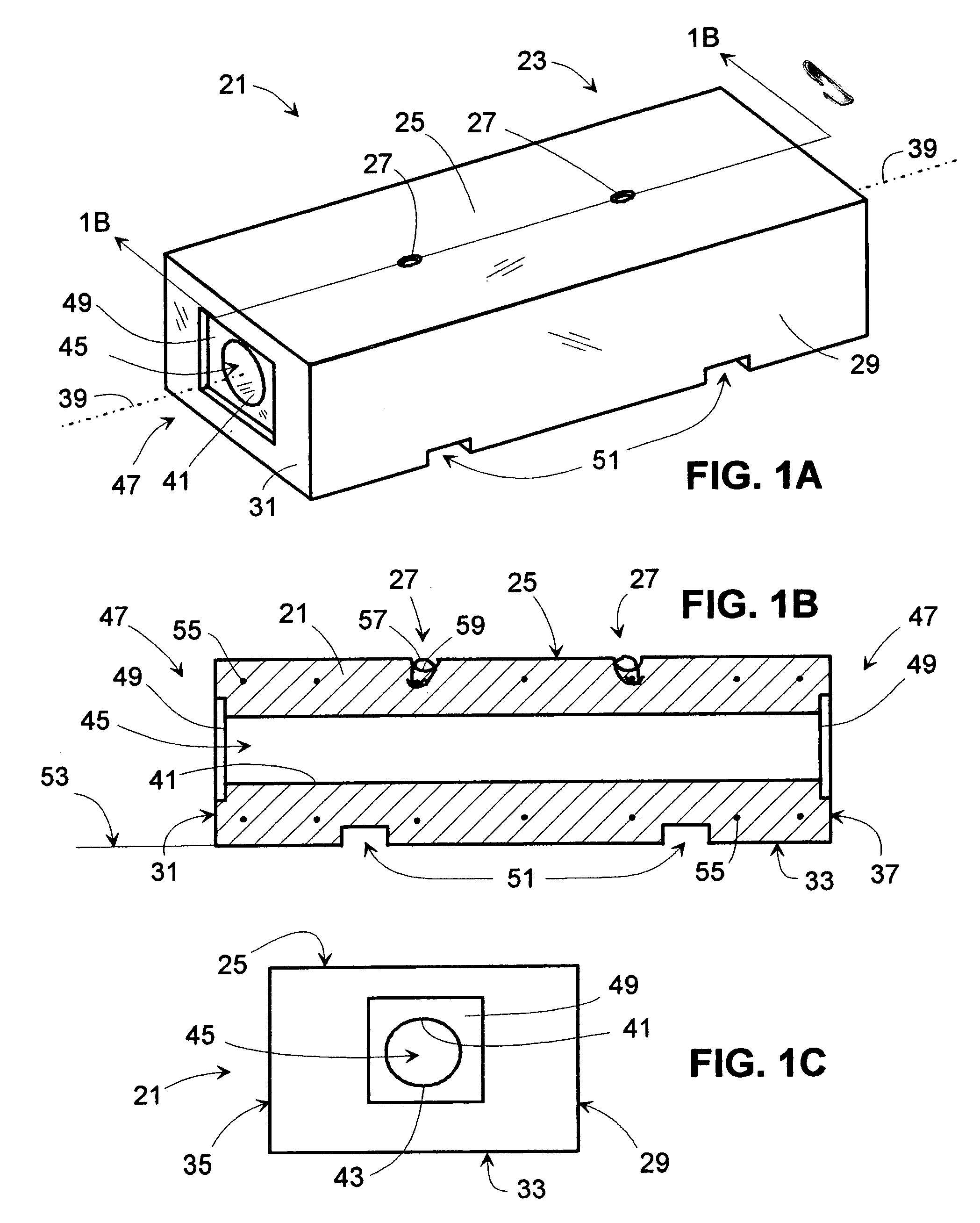
[0068]FIG. 8A shows an end view of an end region 47 of a mass of composite material having a plurality of two tunnels 123. Each tunnel 45 ends with an opening located at a recessed region 49, wherein each tunnel opening and its associated recessed region are identical to those shown in FIG. 1C.

fifth embodiment

[0069]FIG. 8B shows an end view of an end region 47 of a mass of composite material having a plurality of four tunnels 123′. Each tunnel 45 ends with an opening located at a recessed region 49, wherein each tunnel opening and its associated recessed region are identical to those shown in FIG. 1C. When using masses of composite material to build a barrier wall, each mass having one or a plurality of tunnels within them, not all of the tunnels in those with a plurality of tunnels need contain portions of tension cable comprising an overall cable system; however, having masses with a plurality of tunnels provides many options in designing, providing, and perhaps incrementally assembling an effective cable system to hold the masses together.

[0070]FIG. 9A shows two masses of the fourth embodiment 123A and 123B aligned end-to-end and interconnected (interlinked) using a loop of tension cable 125 looped through the two respectively aligned tunnel passageways 45 and 45. The two overlapped s...


PUM


Abstract

Masses of composite material are coupled together by means of one or more cables into a longitudinal barrier wall to provide security from terrorist threats by being able to withstand both vehicle collisions and explosive blasts. The one or more cables are routed through tunnels within the masses. The tunnels have tapered openings to protect cable from being sheared apart when adjacent masses slide relative to one-another. Some of the cable is anchored to some of the masses. Each mass that is located at an end of a barrier wall is used to support anchoring means to anchor some of the cable. Such barrier walls are supported by a surface such as a ground surface and can be dragged along such a surface since a ground anchoring means isn't required. Given sufficient cable, such a barrier wall can withstand great longitudinal tension, and can absorb and endure great amounts of mechanical and thermal energy.

Description

CROSS-REFERENCE TO RELATED APPLICATIONS[0001]This application is a Continuation-In-Part of copending U.S. patent application Ser. No. 10 / 951,951, filed on 28 Sep. 2004, titled “Massive Security Barrier”, assigned to the assignee of the present invention, and incorporated herein by reference.FEDERALLY SPONSORED RESEARCH[0002]Not ApplicableSEQUENCE LISTING OR PROGRAM[0003]Not ApplicableBACKGROUND OF THE INVENTION[0004]1. Field of the Invention[0005]This invention relates to passive barrier elements located on the ground to establish a longitudinal wall that can provide security from terrorist threats by at least slowing, and preferably stopping in a short distance, a vehicle that collides with it, and by providing at least partial protection against blast wave forces, thermal energy, and flying debris from a nearby explosion event.[0006]2. Description of the Related Art[0007]Security zones for protecting sensitive groups of people and facilities, be they private, public, diplomatic, m...

Claims


Application Information

Patent Timeline
IPC IPC(8): E01F13/00E01F13/02E01F15/00E01F15/02E01F15/04
CPCE01F15/083E01F15/088
Inventor NOLTE, ROGER ALLENTULLIS, BARCLAY J.
Owner KONTEK INDS
Why Eureka
Try Eureka