Sealed type electrically driven compressor

Active Publication Date: 2006-12-05
PANASONIC APPLIANCES REFRIGERATION DEVICES SINGAPORE
View PDF15 Cites 15 Cited by
  • Summary
  • Abstract
  • Description
  • Claims
  • Application Information

AI Technical Summary

Benefits of technology

[0019]Further, a divider shaped like a flat plate is inserted in and engaged with the slanting channel. The divider prevents oil from slipping in the slanting channel and ensures stable lubrication especially in operation at low rotational speeds.
[0020]The divider is shaped like a vertically symmetrical flat plate. The divider has a semi-circular notch in substantially the center at least at the bottom end. The divider also has a press fit portion in which the width of almost the longitudinal center is larger than those of the top and bottom ends. The semi-circular notches provided at the both ends of the divider keeps the ratio of two divided openings of the inlet port in the throttle unchanged even when the bottom end of the divider is displaced from the center of the throttle. Increasing the width of the portion in the vicinity of the longitudinal center allows the divider to be inserted from any of the top and bottom ends thereof and prevents the divider from curving, thus increasing the workablity in assembling.
[0021]Further, a step is provided in a position in the direction of the depth of the slanting channel from the bottom end thereof. The distance from the bottom end of the slanting channel to the step is equal to the length of the divider. This constitution allows the slanting c

Problems solved by technology

This causes a serious problem in the operation at a lower rotational speed.
This causes a drawback of delivering an insufficient amount of the lubricating oil to the sliding part in the upper portion.
However, this prior art has a complicated path of lubricating oil and a complicated constitution, and thus requires a large number of components.
This causes

Method used


Image

  • Sealed type electrically driven compressor
  • Sealed type electrically driven compressor
  • Sealed type electrically driven compressor

Examples


first exemplary embodiment

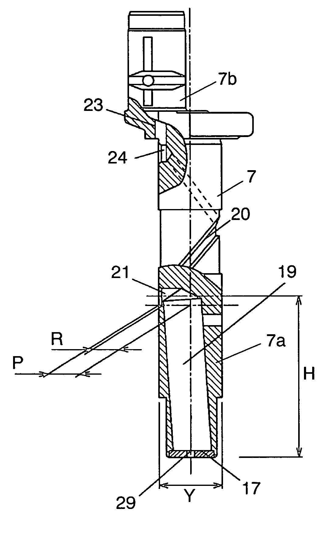
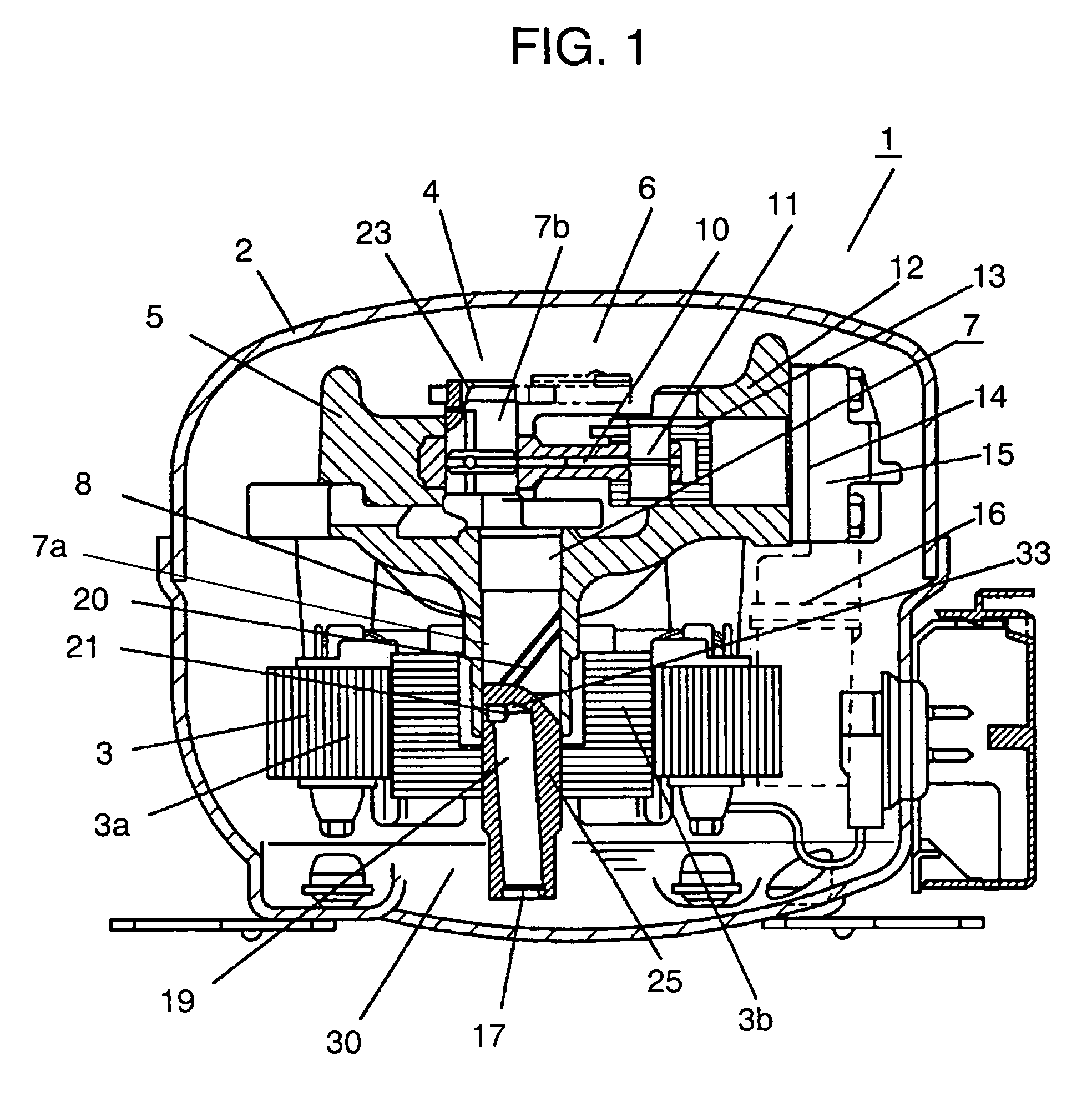
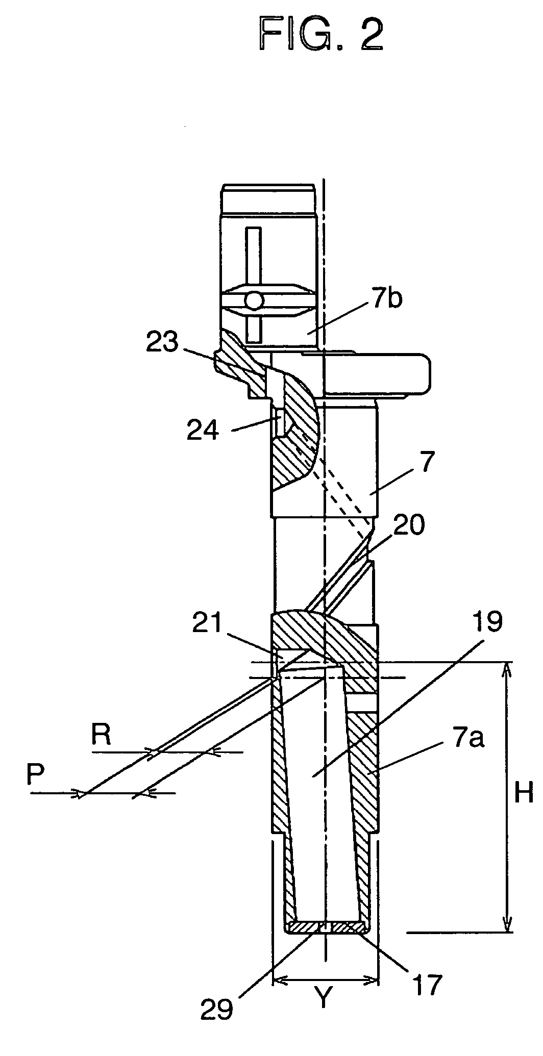
[0040]FIG. 1 is a sectional view of a hermetic electric compressor in accordance with the first exemplary embodiment of the present invention. FIG. 2 is a sectional view of an essential part of a crankshaft in accordance with the first exemplary embodiment. FIG. 3 is a sectional view of an essential part of the crankshaft in accordance with the first exemplary embodiment, showing how a lubricating oil is pumped up.

[0041]A hermetic electric compressor body 1 is constituted to house an electric motor 3 comprising a stator 3a and a rotor 3b, and a compressing unit 6 integrated a compressing mechanism 4 by a cylinder block 5 in upper and lower hermetic shell 2. A main crankshaft 7a of a crankshaft 7 is supported by a bearing 8 of a cylinder block 5. Coupled to an eccentric crankshaft 7b in the upper portion of the crankshaft 7 is a connecting rod 10. Coupled to the connecting rod 10 is a piston 13 for sliding via a piston-pin 11 in a cylinder 12. A valve plate 14 includes a suction port...

second exemplary embodiment

[0056]FIG. 7 is an enlarged sectional view of a lower portion of a main crankshaft in accordance with the second exemplary embodiment of the present invention.

[0057]As shown in FIG. 7, at the bottom end of the main crankshaft 7a, an extended tubular part 18 and a throttle 17 are formed. The slanting channel 19 serving as a passage for a lubricating oil is bored from a top end of the extended tubular part 18 so as to incline with respect to the center axis of the main crankshaft 7b. The internal diameter of the extended tubular part 18 is formed larger than the diameter of the slanting channel 19. A cap 31 shaped like a flat disk is inserted along and engaged with the inner peripheral of the extended tubular part 18. The cap 31 is formed by punching an ordinary steel stock or the like, and has an inlet port 29 for sucking the lubricating oil 30 at the center thereof. The throttle 17 is a generic term including the extended tubular part 18 and the cap 31 having the inlet port 29.

[0058...

third exemplary embodiment

[0065]FIG. 9 is an enlarged sectional view of a lower portion of a main crankshaft in accordance with the third exemplary embodiment of the present invention. FIG. 10 is a perspective view of a divider. FIG. 11 is an enlarged sectional view of the D portion of FIG. 9.

[0066]An extended tubular part 18 is formed at the bottom of a main crankshaft 7a. The slanting channel 19 is a passage for lubricating an oil provided from the top end of the extended tubular part 18. The inner diameter of the slanting channel 19 includes the center of the extended tubular part 18. A divider 26 is shaped like a thin flat plate that is press-fitted into the slanting channel 19. The divider 26 has a semi-circular notch 27 at each of the top and bottom ends thereof. The divider 26 is formed symmetrically at the upper and lower sides so that it can be inserted from any of top and bottom ends. The divider 26 has a press fit portion 28 in which substantially an intermediate portion of the divider is formed s...


PUM


Abstract

A hermetic electric compressor is capable of efficiently pumping up a necessary amount of lubricating oil even at low-speed rotation and has a simple constitution to provide an excellent workablity in assembling. The hermetic electric compressor includes an oil pump. The oil pump includes (i) a slanting channel formed in the lower portion of a main shaft and slanting from the lower portion to the upper portion thereof outwardly, (ii) a throttle formed at the bottom end of the main shaft and having an inlet port of diameter smaller than the section of the slanting channel at the center thereof, and (iii) a lower communicating passage for providing a communication between the bottom end of a spiral groove and the slanting channel. This constitution is capable of effectively lift the head of the lubricating oil.

Description

FIELD OF THE INVENTION[0001]The present invention relates to a hermetic electric compressor for use in freezing and refrigerating equipment or a room air-conditioner. It more particularly relates to an oiling and lubricating system for supplying lubricating oil reserved in a hermetic shell to rotating and sliding parts in the hermetic electric compressor by a centrifugal force of a rotation of a crankshaft.BACKGROUND OF THE INVENTION[0002]Recently, there has been a strong demand for reduction in power consumptions and noise in a hermetic electric compressor for use in a domestic freezer and refrigerator or a room air-conditioner. For a reduction in power consumptions and a noise, an inverter-driven compressor is operated at a lower rotational speed (e.g. approx. 1,800 revolutions per minute (rpm) for a domestic refrigerator).[0003]On the other hand, many lubricating oil pump systems for a hermetic electric compressor utilize a centrifugal force resulting from a rotation of a cranksh...

Claims


Application Information

Patent Timeline
IPC IPC(8): F04B17/00F01M1/04F04B35/04F01M1/00F04B39/00F04B39/02
CPCF04B39/0246F04B39/0253F04B39/0261F04B39/02
Inventor ISHIDA, YOSHINORIOTA, TOSHIHIKOIDE, TERUMASAKATAYAMA, MAKOTOHORIGUCHI, TAKAFUMINAGAO, TAKAHIDE
Owner PANASONIC APPLIANCES REFRIGERATION DEVICES SINGAPORE
Why Eureka
Try Eureka