Endovascular prosthesis, system and method

a prosthesis and endovascular technology, applied in the field of endovascular prosthesis, system and method, can solve the problems of vascular patient danger, significant risk of death or disability, applicability of these prostheses, etc., to achieve accurate branch endograft placement, reduce diameter, and facilitate endograft placemen

Inactive Publication Date: 2006-12-05
COOK MEDICAL TECH LLC +1
View PDF10 Cites 140 Cited by
  • Summary
  • Abstract
  • Description
  • Claims
  • Application Information

AI Technical Summary

Benefits of technology

[0009]An advantage of the present invention is that it provides a reduced diameter midsection on which one or more side branches may be placed thereby allowing maneuvering of branch endografts to connect between side ports and native branches.
[0010]Another advantage of the present invention is that the side ports on the midsection may be positioned and aligned to facilitate easy placement of endografts through them into branch vessels.
[0011]Another advantage of the present invention is that the side ports allow for accurate branch endograft placement without kinking despite variations in location of native vessels.
[0012]Another advantage of the present invention is that the location of the side ports in the reduced diameter midsection of the prosthesis reduces the overall diameter of the device for easier insertion.
[0013]Another advantage of the present invention is that the prosthesis of the present invention is able to connect to commercially available thoracic, abdominal and branch endografts to allow repair of the entire aorta and its branches.
[0014]Another advantage of the present invention is that the prosthesis may be modified by variation in side port arrangement for use in the aortic arch, suprarenal or juxtarenal positions.

Problems solved by technology

Conventional open surgery for arterial replacement is associated with significant risk of death or disability and may be especially dangerous for the vascular patient who typically has significant pre-existing surgical risk factors.
A limitation on the applicability of these prostheses has been their inability to repair branched arteries.
Although grafts have been designed with end branches to accommodate the iliac arteries, no commercially available device exists with side branches to accommodate the thoracic and abdominal aortic branches.
This is often difficult or impossible in actual practice owing to the variability in individual patient anatomy and the difficulty of accomplishing this precise alignment in vivo.
This approach has also been limited by the need for precise alignment of the side-holes with the native arterial branch origins.
This is difficult to accomplish in vivo, again owing to the variability of anatomy of individual patients and difficulties in obtaining precise alignment of the prosthesis at the time of implantation.
Small measurement errors may result in either longitudinal or circumferential misplacement of these side holes, and this may result in the kinking of the branch endografts as they attempt to reach the native branch vessel.
This design is limited by crowding of multiple branches within the native aorta which may lead to radiographic confusion in their identification and limit their ability to be manipulated within a confined space.
In addition, the necessary use of multiple long sheets of small tubular conduits may be prone to thrombosis and graft failure.
The multiple end branches may also be prone to kinking as the end branches interweave on their paths to the various end arteries.
As each of the end branches is deployed each successive branch will be more difficult to maneuver in the crowded lumen of the aorta.

Method used


Image

  • Endovascular prosthesis, system and method
  • Endovascular prosthesis, system and method
  • Endovascular prosthesis, system and method

Examples


Embodiment Construction

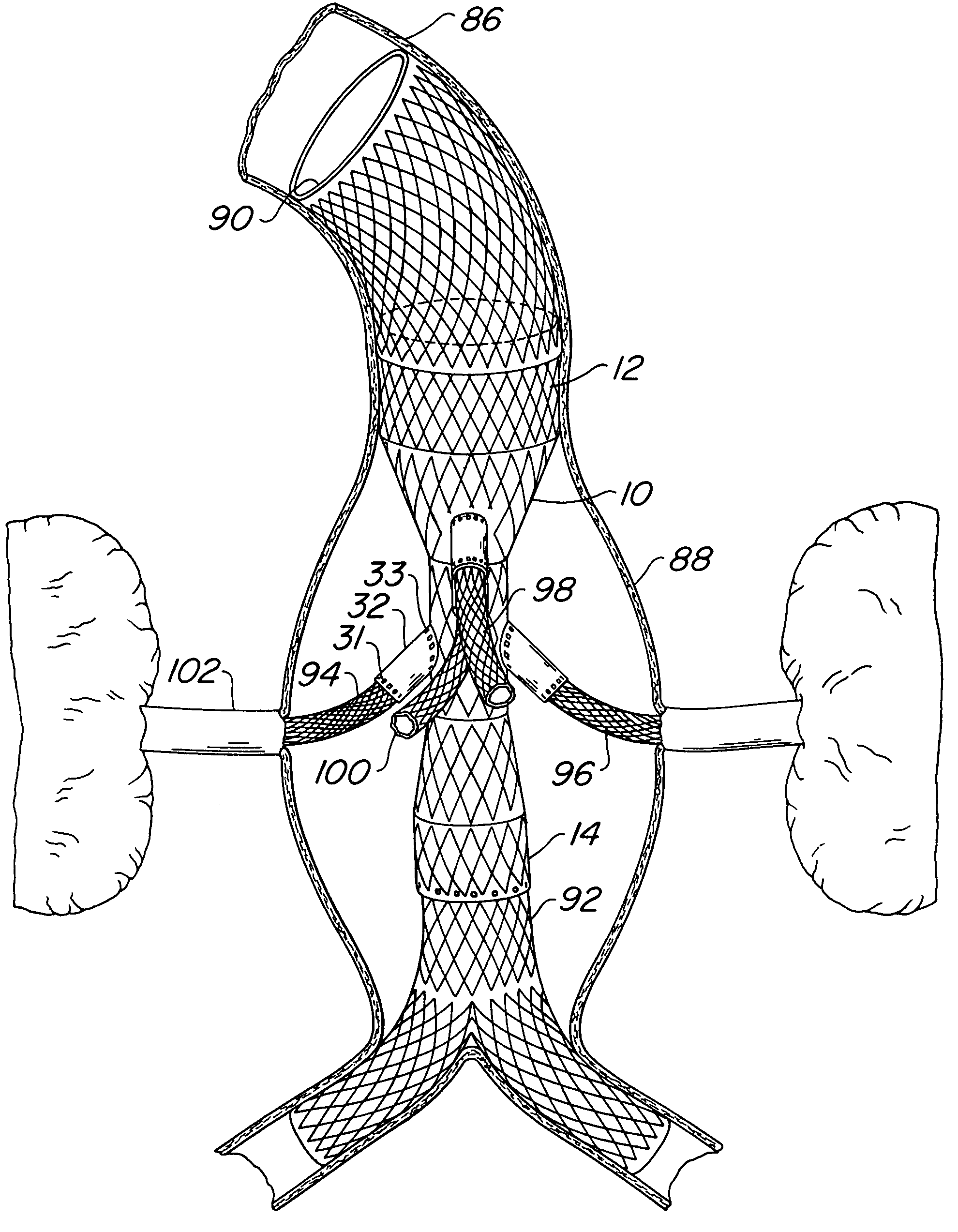
[0030]Referring now to the drawings wherein like numerals indicate like elements, there is shown in FIG. 1 an endovascular prosthesis 10 in accordance with the present invention. Endovascular prosthesis 10 is provided with a first end section 12 and a second end section 14. Both first end section 12 and second end section 14 have a longitudinally extending central lumen and means 16 and 18, respectively, for laterally supporting first end section 12 and second end section 14, respectively. The means for laterally supporting the first end section 12 and second end section 14, as well as midsection 20 to be discussed, may be any suitable means for providing lateral support, but in a presently preferred embodiment, the lateral support means may be a resilient stent formed on the outer surface of endovascular prosthesis 10 as illustrated in FIG. 1 which may be compressed, but automatically expands upon release of the compressing force.

[0031]Midsection 20 is formed between first end sect...


PUM


Abstract

An endovascular prosthesis comprising a first end section, a second end section and a midsection. The midsection has a diameter less than the diameter of the first end section and the second end section. At least the first end section and the second end section have lateral support preferably in the form of a stent which may also act as anchoring. The reduced diameter midsection is provided with at least one side port which is adapted to be connected to a branch endograft to provide a connection between the side port and the native branch artery. The side ports are arranged to correspond with the native branch arteries and are provided with radiographic markers at their proximal and distal ends. The side ports with the radiographic markers provide an effective means of making the connection to the native branch by a branch endograft without having to align the side ports exactly to the branch arteries and without kinking of the side ports.

Description

FIELD OF THE INVENTION[0001]The present invention relates to an endovascular prosthesis, system and method. More particularly, the present invention relates to an endovascular prosthesis which provides improved connection between the endovascular prosthesis which may be positioned in a major artery, such as the aorta, and branch arteries. The present invention also relates to a system and method of endovascular prosthesis placement.BACKGROUND OF THE INVENTION[0002]Degenerative diseases of the arteries such as aneurysms and dissections often necessitate arterial replacement. Conventional open surgery for arterial replacement is associated with significant risk of death or disability and may be especially dangerous for the vascular patient who typically has significant pre-existing surgical risk factors.[0003]Minimally invasive alternatives to open vascular surgery have been developed, chiefly employing endovascular means whereby arterial replacement is performed by placement of an en...

Claims


Application Information

Patent Timeline
Patent Type & Authority Patents(United States)
IPC IPC(8): A61F2/06A61F2/00A61F2/82
CPCA61F2/07A61F2/954A61F2002/061A61F2002/067A61F2002/075A61F2002/821A61F2250/0039A61F2250/0098A61F2/89A61F2/90A61F2002/072A61F2230/0067
Inventor CARPENTER, JUDITH T.CARPENTER, JEFFREY P.
Owner COOK MEDICAL TECH LLC
Why Eureka
Try Eureka