Arc suppression circuit for electrical contacts

a technology of arc suppression circuit and electrical contacts, which is applied in the direction of circuit-breaking switches, circuit-breaking switches for excess current, circuit-breaking switch details, etc., can solve the problems of arc traversing across the relay contact, the voltage across the inductive load to rise rapidly, and the magnetic field to collapse, so as to reduce the probability of arcing, reduce the back emf generated across the inductive load, and the capacitor charge more slowly

Active Publication Date: 2006-12-05
TYCO ELECTRONICS LOGISTICS AG (CH)
View PDF6 Cites 30 Cited by
  • Summary
  • Abstract
  • Description
  • Claims
  • Application Information

AI Technical Summary

Benefits of technology

[0007]It is an object of the present invention to overcome the disadvantages described above by providing a circuit configured to suppress arcing across electrical contacts, for example, the electrical contacts of a relay, which may operate using a relatively small capacitor. For this purpose, a switching device, for example, a FET device, is arranged in parallel across both the capacitor and the contacts of the relay. The switching device turns on when the relay contacts are opened, thereby providing an alternate path for the current generated by the inductive load. Since current is diverted (i.e., snubbed) through the FET device, the capacitor charges more slowly, thereby reducing both the back EMF generated across the inductive load and the probability of arcing across the relay contacts.
[0008]By reducing the probability of arcing, a relay having a lower voltage rating may be used in applications requiring relays having higher voltage ratings. For example, the arc suppression circuit according to the present invention may permit a 12V relay to be used in place of a 42V relay in automobile applications.

Problems solved by technology

At a subsequent time, the relay contacts open, thereby causing the magnetic field to collapse.
However, since current flow through an inductor cannot change instantaneously, a back EMF is generated across the inductive load, which causes the voltage across the inductive load to rise rapidly.
This rapid rise in voltage (i.e., a voltage spike) may cause an arc to traverse across the relay contacts.
Over a period of time, such arcing may cause, for example, deposits on the relay contacts, thereby reducing the effectiveness of the relay contacts.
However, such large capacitors result in increased cost and circuit size.

Method used


Image

  • Arc suppression circuit for electrical contacts
  • Arc suppression circuit for electrical contacts
  • Arc suppression circuit for electrical contacts

Examples


Embodiment Construction

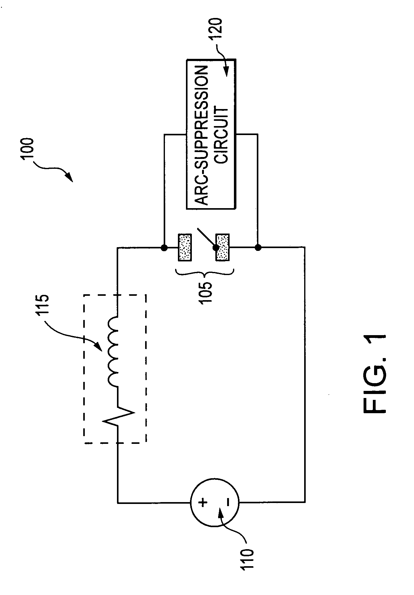
[0017]Referring now to FIG. 1, there is seen a first exemplary circuit 100 according to the present invention. Arc suppression circuit 100 includes relay contacts 105 coupled in series with a power supply 110 and an inductive load 115. First exemplary circuit 100 also includes an arc suppression circuit 120 coupled in parallel with relay contacts 105. The relay coil is not shown in any of the Figures.

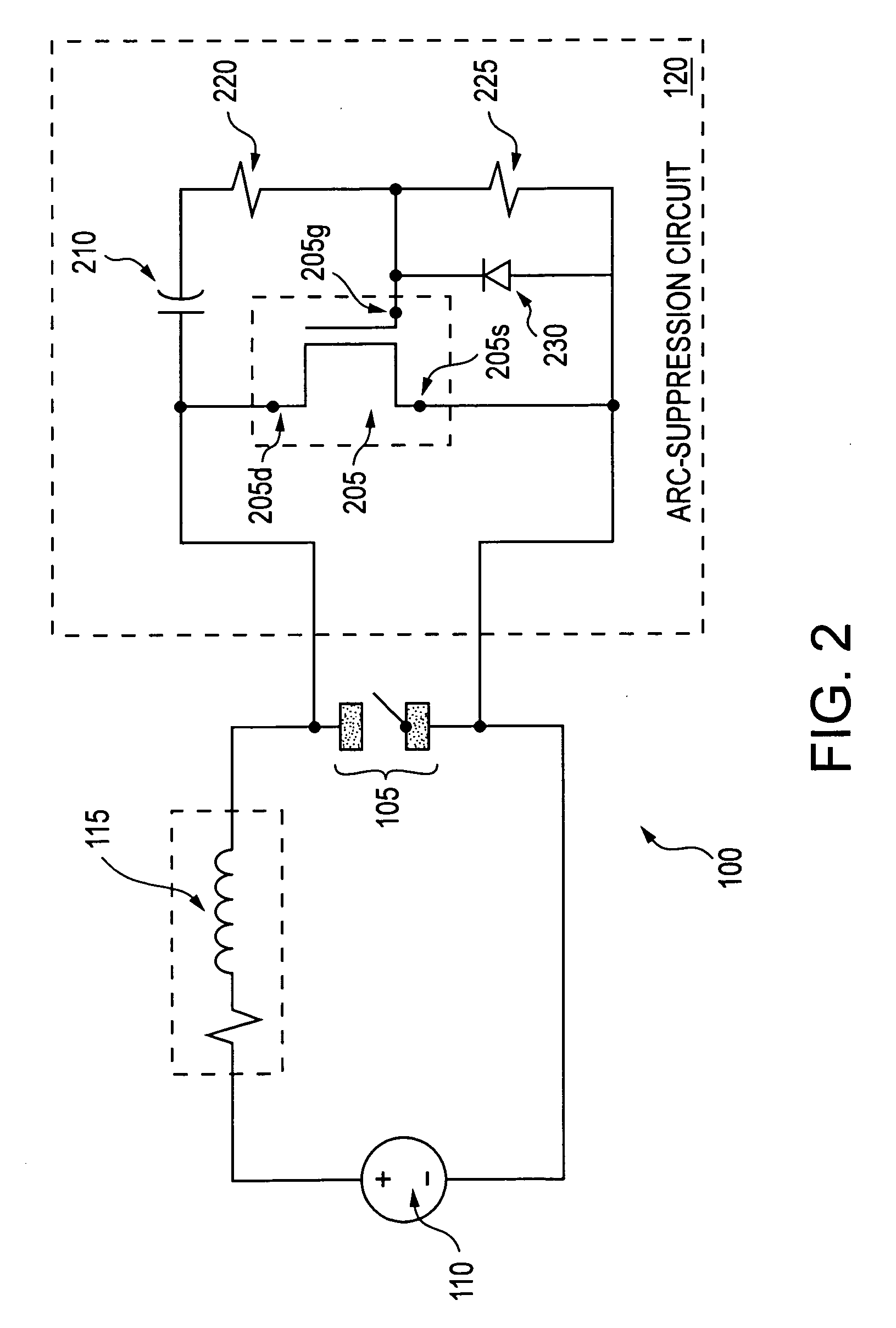
[0018]Referring now to FIG. 2, there is seen the first exemplary circuit 100 of FIG. 1, in which the arc suppression circuit 120 includes a FET switch 205 electrically coupled in parallel with relay contacts 105, a capacitor 210 electrically coupled to drain 205d of FET switch 205, a first resistor 220 electrically coupled between capacitor 210 and gate 205g of FET switch 205, a second resistor 225 electrically coupled between gate 205g of FET switch 205 and source 205s of FET switch 205, and a diode 230 electrically coupled between gate 205g of FET switch 205 and source 205s of FET swi...


PUM


Abstract

A circuit to suppress arc across contacts of a relay is provided, in which the relay is electrically coupled to a power supply and a load. The circuit includes an arc suppression circuit electrically coupled between the first and second contacts of the relay, and the arc suppression circuit includes a capacitor and a switch, both of which are electrically coupled to the first and second contacts of the relay, in which the switch is configured to turn on when the first and second contacts of the relay change state, thereby providing an alternate path for a current flow through the load.

Description

RELATED APPLICATIONS[0001]The present application is based on and claims the benefit of U.S. Provisional Application Ser. No. 60 / 381,662, filed on May 17, 2002, entitled ARC SUPPRESSING CIRCUIT FOR ELECTRICAL CONTACTS, and the present application is based on and claims the benefit of U.S. Provisional Application Ser. No. 60 / 412,630, filed Sep. 19, 2002, entitled ARC SUPPRESSING CIRCUIT FOR ELECTRICAL CONTACTS, the entire contents of both of which are expressly incorporated herein by reference.FIELD OF THE INVENTION[0002]The present invention relates to an arc suppression circuit for electrical contacts, and in particular, for relay contacts.BACKGROUND INFORMATION[0003]In many applications, it may be necessary to prevent voltage arcing across electrical contacts, for example, to prevent arcing across electrical contacts of a relay. With respect to inductive loads, such motors, closing of the relay contacts causes a magnetic filed to be generated in the load. At a subsequent time, the...

Claims


Application Information

Patent Timeline
Patent Type & Authority Patents(United States)
IPC IPC(8): H01H9/30H01H9/54
CPCH01H9/542H01H2009/546
Inventor KING, RAYBRYAN, LYLE
Owner TYCO ELECTRONICS LOGISTICS AG (CH)
Why Eureka
Try Eureka