Scan diagnosis system and method

a diagnostic system and scan technology, applied in the direction of instruments, digital computer details, program control, etc., can solve the problems of increasing the volume of functional test pattern data required to achieve acceptable fault coverage, increasing the cost of conventional functional test approaches, and complicating the process, so as to optimize the design-to-production timetable and minimize the diagnosis time

Active Publication Date: 2006-12-05
TERADYNE
View PDF12 Cites 15 Cited by
  • Summary
  • Abstract
  • Description
  • Claims
  • Application Information

AI Technical Summary

Benefits of technology

[0011]The DFT result diagnosis system and method of the present invention provides a unique automated and visual approach to testing semiconductor devices with ATE and DFT tools. This minimizes diagnosis time for devices-under-test, thereby optimizing the design-to-production timetable for semiconductor devices.

Problems solved by technology

However, as device complexities and densities increase, the cost of the conventional functional test approach can increase dramatically.
In particular, the volume of functional test pattern data required to achieve acceptable fault coverage may increase exponentially with the size of the device.
However, to make use of these tools, the device must generally be tested using the ATPG patterns, and the failures captured on the tester must somehow be routed back to the diagnosis tool.
Therefore, result translation generally requires some knowledge of how the ATPG patterns were translated into manufacturing test patterns, thus complicating the process.
By correlating test failures to physical defects, they allegedly reduce the number of hardware samples submitted to failure analysis technicians.
While the conventional techniques described above are beneficial for their intended purposes, the lack of automation between the ATE and the diagnosis tool is problematic.
Moreover, the failure data identified and processed is typically not readily user-comprehensible.

Method used


Image

  • Scan diagnosis system and method
  • Scan diagnosis system and method
  • Scan diagnosis system and method

Examples


Embodiment Construction

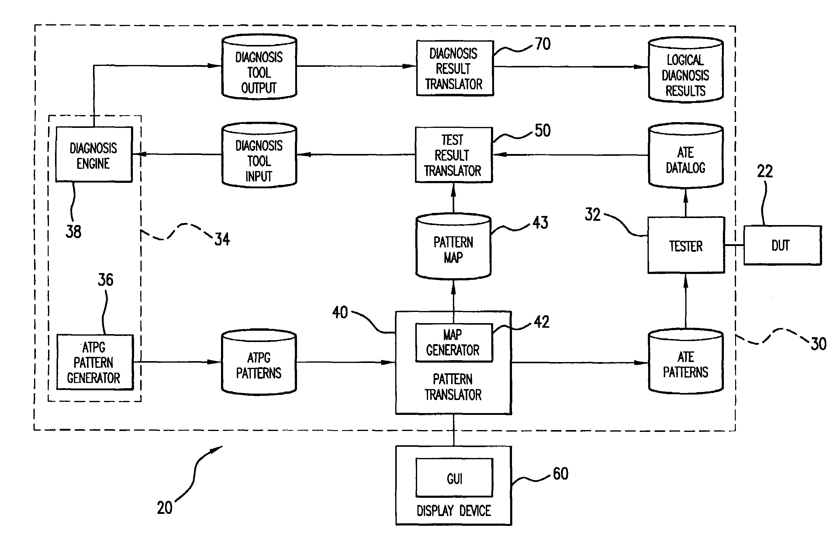
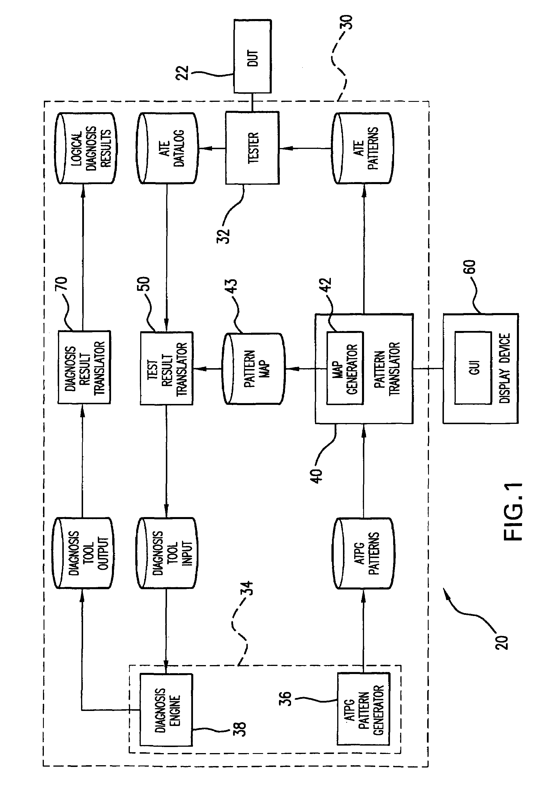
[0023]Electronic design automation (EDA) software gives semiconductor device manufacturers a tool for troubleshooting and refining their circuit designs before entering mass production. Employing EDA tools with production-oriented ATE provides real-world test solutions not only for the pre-production stage, but also in post-production where new failures may materialize that might be indetectable through simulation alone. The present invention seamlessly integrates EDA software with the ATE software to create a DFT result diagnosis system, generally designated 20 (FIG. 1), to fully automate the process.

[0024]Referring to FIG. 1, the DFT result diagnosis system 20, in one form comprises a scan diagnosis system that employs a test and diagnosis engine 30 that couples to a device-under-test (DUT) 22. A graphical-user-interface (GUI) 60 ties-in to the test and diagnosis engine to provide real-time visual monitoring of the various functions provided by the present invention, more fully de...


PUM


Abstract

A scan diagnosis system for testing and diagnosing a device-under-test is disclosed. The system includes a semiconductor tester adapted for coupling to the device-under-test and operative to generate pattern signals in the ATE domain to test the device-under-test and produce test output data in the ATE domain. An ATPG diagnosis tool is operative to generate ATPG pattern data and ATPG results data in the ATPG domain. A translator serves to effect automatic correlation of data between the ATPG domain and the ATE domain to allow data communication between the tester and the tool.

Description

FIELD OF THE INVENTION[0001]The invention relates generally to automatic test equipment and more particularly a DFT result diagnosis system and method for designing, testing and diagnosing semiconductor devices.BACKGROUND OF THE INVENTION[0002]Conventional automatic test equipment (ATE) tests semiconductor devices using the functional test approach. The goal of the functional test approach is to verify that the device performs its intended function under a variety of realistic operating conditions. Use of the functional test approach typically requires the generation of functional test patterns which exercise the device through its external interface.[0003]However, as device complexities and densities increase, the cost of the conventional functional test approach can increase dramatically. In particular, the volume of functional test pattern data required to achieve acceptable fault coverage may increase exponentially with the size of the device. To offset these costs, many semicon...

Claims


Application Information

Patent Timeline
Patent Type & Authority Patents(United States)
IPC IPC(8): G06F17/50G01R31/317G01R31/3183
CPCG01R31/31707G01R31/31718G01R31/3172G01R31/3183G01R31/318342G01R31/31835
Inventor VARNEY, ROBERT
Owner TERADYNE
Why Eureka
Try Eureka