Parts washer system

a technology of washer and parts, applied in the field of industrial machinery, can solve the problems of manufacturing plant dirt, machining burrs, and conventional devices that have little application in the industrial parts industry, and achieve the effects of reducing cycle time, reducing cleaning costs, and facilitating the determination of industrial parts' cleanliness

Active Publication Date: 2006-12-12
CINETIC AUTOMATION
View PDF98 Cites 13 Cited by
  • Summary
  • Abstract
  • Description
  • Claims
  • Application Information

AI Technical Summary

Benefits of technology

[0005]The present invention is advantageous over conventional machines in that the present parts washer easily determines the cleanliness of an industrial part in a non-obtrusive and real time manner. Thus, the cleaning cycle can vary from part-to-part as needed. Accordingly, cleaning quality is improved for parts having excessive burrs and debris while cycle time is quickened for

Problems solved by technology

These conventional devices, however, appear to have little application in the industrial parts industry for cle

Method used


Image

  • Parts washer system
  • Parts washer system
  • Parts washer system

Examples


Embodiment Construction

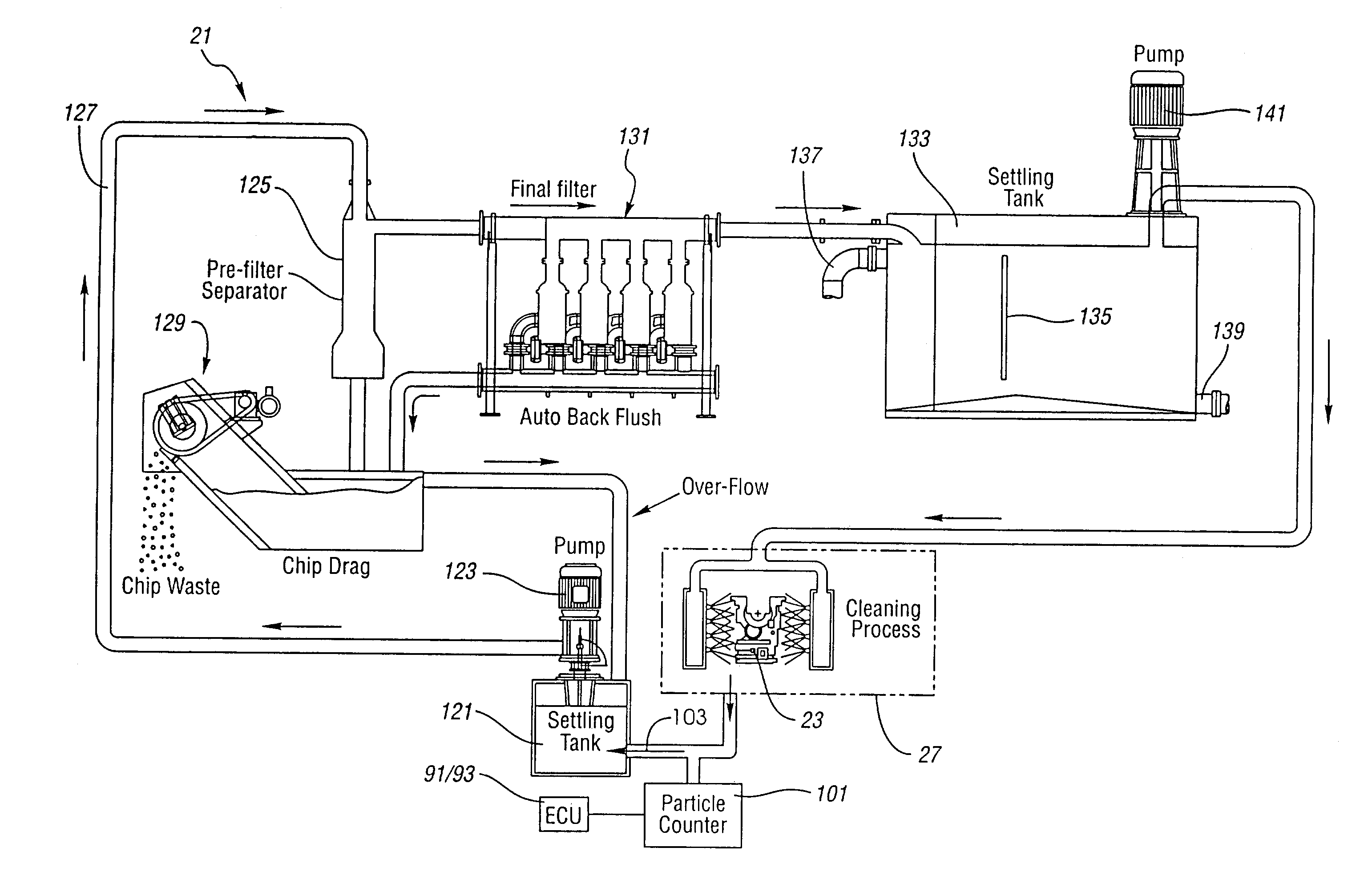
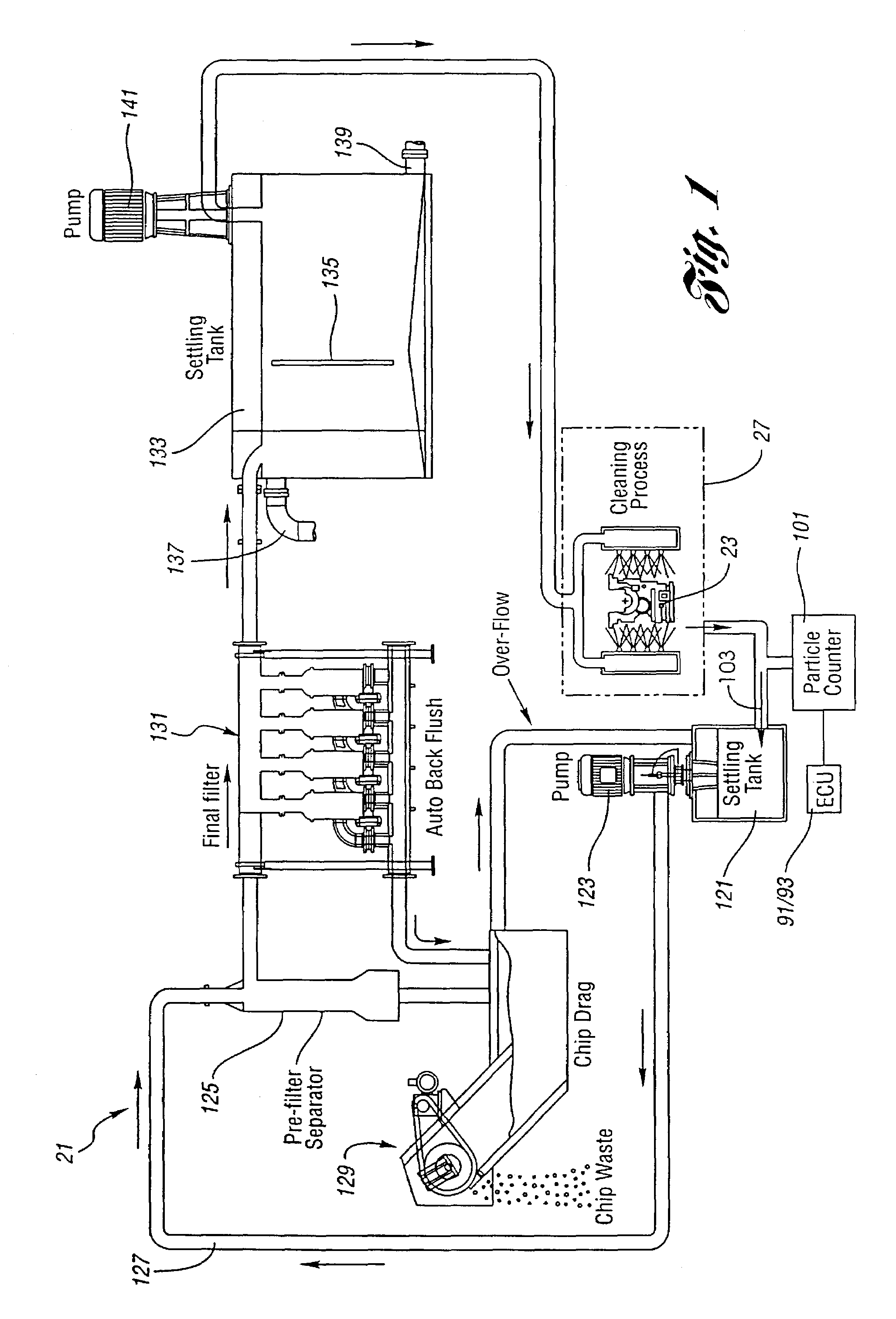
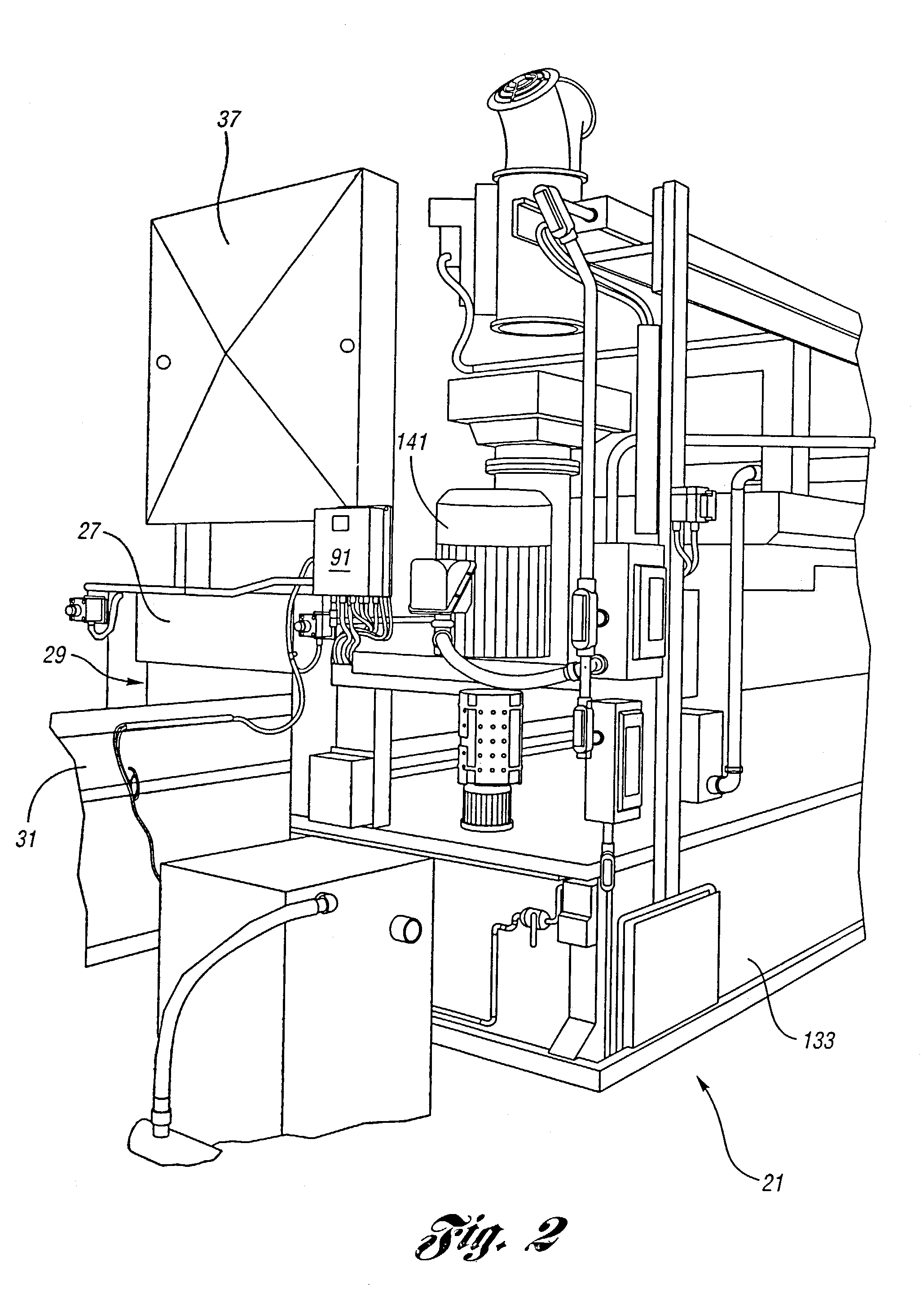
[0017]Referring to FIGS. 1, 2, 4 and 6, the preferred embodiment of a parts washer system 21 is used in an industrial manufacturing plant to clean machining burrs, grease, dirt and other manufacturing debris from industrial parts or workpieces such as automotive vehicle powertrain components, including an engine block 23 (see FIG. 1), a metallic crankshaft 25 (see FIGS. 4 and 6), or the like. Parts washer system 21 operates as a cleaning station after a machining station (not shown) where the part has elongated internal pasageways or other features added by a milling machine, lathe, or similar automatic tools. Parts washer system 21 includes a sheet metal housing 27 affixed to the factory floor. Housing 27 essentially encloses the parts cleaning station yet has an entryway 29 for allowing access entry and exit by a horizontally moving shuttle 31 or other type of automatically operating conveyor. Shuttle 31 has a pair of parallel rails 33 upon which are mounted spaced apart perches 3...


PUM

PropertyMeasurementUnit
Flow rateaaaaaaaaaa
Shapeaaaaaaaaaa
Turbidityaaaaaaaaaa

Abstract

An industrial parts washer system includes washing fluid, an assembly operable to apply the washing fluid to the part, a turbidity sensor coupled to the assembly operable to sense a condition of the washing fluid after the fluid washes the part, and a control unit connected to the sensor that compares the sensed condition of the washing fluid to a value and thereby determines whether the part should be washed further.

Description

BACKGROUND OF THE INVENTION[0001]The present invention relates generally to industrial machinery and more specifically to a parts washer system.[0002]Industrial parts washers are commonly used to remove debris, such as machining burrs, grease and dirt, from metallic parts such as engine blocks and crankshafts. Two such conventional devices are disclosed in Canadian Patent No. 669,262 entitled “Washing Apparatus” which issued to Umbricht on Aug. 27, 1963, and United Kingdom Patent No. 817,851 entitled “Improvements in or Relating to Washing Apparatus” which was published on Aug. 6, 1959. Another known industrial parts washer is disclosed in U.S. Pat. No. 3,059,861 entitled “Adjustable Spray Nozzle Assembly” which issued to Umbricht et al. on Oct. 23, 1962, and is incorporated by reference herein. Many traditional industrial parts washers typically flow a cleaning liquid onto the part for a predetermined period of time regardless of how clean the part actually is and regardless of par...

Claims


Application Information

Patent Timeline
IPC IPC(8): B08B3/02B08B3/00B08B3/14B08B9/00C23G1/36C23G3/00
CPCB08B3/00B08B3/02B08B3/14B08B9/00C23G1/36C23G3/00
Inventor STOCKERT, DAVID L
Owner CINETIC AUTOMATION
Why Eureka
Try Eureka