Pulse generator for an ultrasound flowmeter

Inactive Publication Date: 2006-12-12
ENDRESS HAUSER FLOWTEC AG
View PDF2 Cites 1 Cited by
  • Summary
  • Abstract
  • Description
  • Claims
  • Application Information

AI Technical Summary

Benefits of technology

[0015]An essential idea of the invention is to arrange the RC-member between the voltage supply unit and the switch, in order to decrease the pulse voltage, when the switch is driven at a too high r

Problems solved by technology

With small pulse-voltages, signal evaluation becomes extrem

Method used


Image

  • Pulse generator for an ultrasound flowmeter
  • Pulse generator for an ultrasound flowmeter
  • Pulse generator for an ultrasound flowmeter

Examples


Embodiment Construction

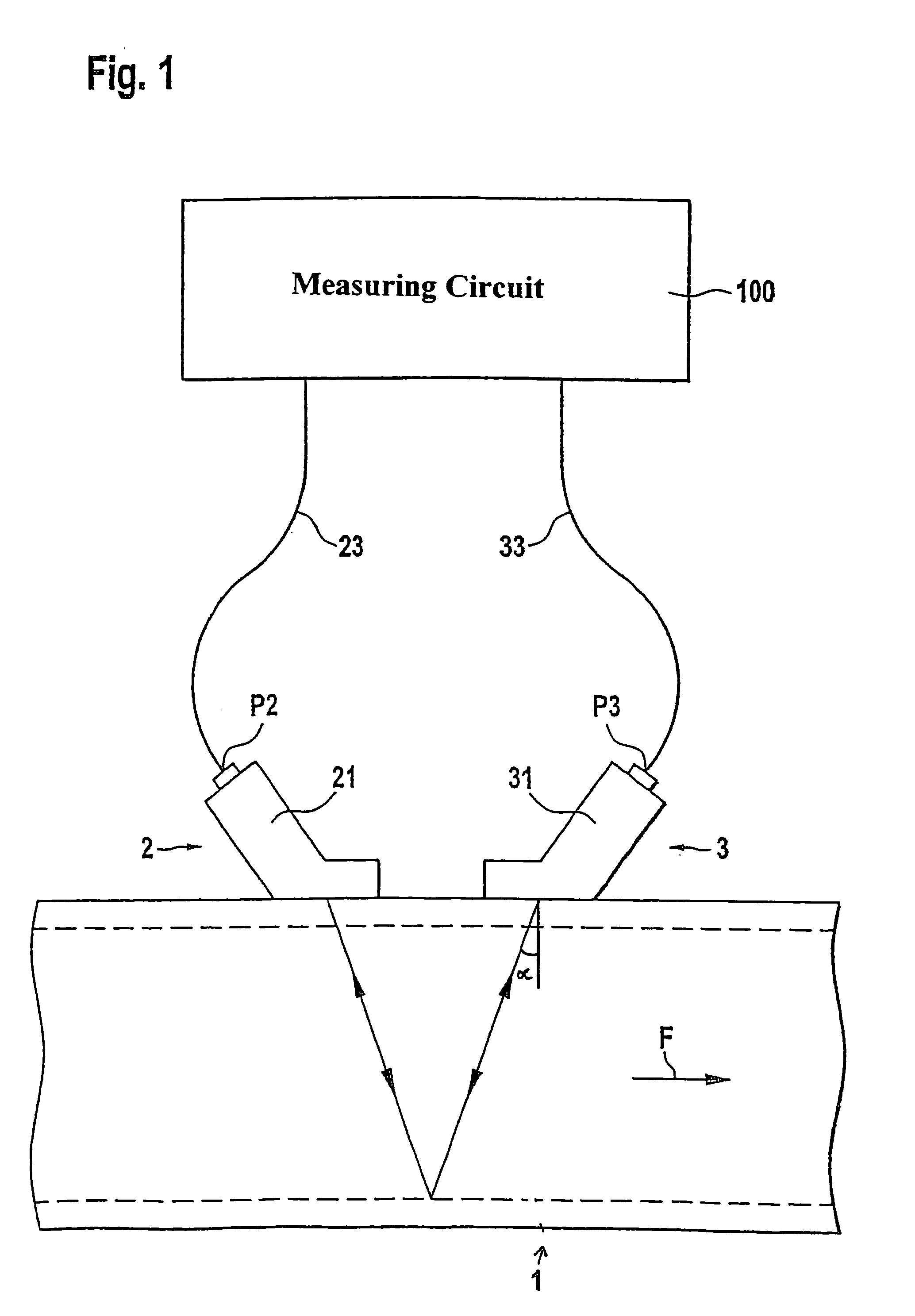
[0020]FIG. 1 shows, in greatly simplified manner, an ultrasonic flow measuring device possessing two ultrasonic transducers 2, 3, which are arranged axially-parallel and displaced from one another on the outer wall of a pipeline 1. The liquid F in the pipeline 1 is flowing in the direction of the arrow.

[0021]This transducer pair can be operated in two different ways. Either the ultrasonic transducer 2 acts as transmitting transducer and the ultrasonic transducer 3 as the receiving transducer, or the ultrasonic transducer 2 as the receiving transducer and the ultrasonic transducer 3 as the transmitting transducer, so that, alternatingly, measurement is in the flow direction or opposite to the flow direction.

[0022]Each ultrasonic transducer 2, 3 is composed of a piezoelement P2, P3 and a coupling element 21, 31, which either couples the ultrasonic signals at an angle á less than 90-degrees into or out of the wall of the pipeline. The angle á is chosen such that as flat an angle as pos...


PUM


Abstract

A pulse generator including a control logic operating, by control pulses, a switch connected on the input side with a voltage supply unit and delivering a pulse voltage on the output side, there is connected, between control logic and the switch, a capacitor, which decreases the pulse voltage when the pulse frequencies are too low, and, additionally, arranged between voltage supply unit and switch, an RC-member, which decreases the pulse voltages when the repetition rates of the control pulses are too high, in order to enable use of the pulse generator in the explosion-protected area.

Description

FIELD OF THE INVENTION[0001]The invention relates to a pulse generator comprising a control logic, which drives by means of control pulses a switch, which is connected on the input side with a voltage supply unit and delivers a pulse voltage on the output side.BACKGROUND OF THE INVENTION[0002]Such pulse generators are used in many applications in the field of process automation with reference to its applications of ultrasonics and radar.[0003]Thus, the ultrasonic flow measuring devices permit, in a simple manner, contact-less determination of volume flow rate in a pipeline.[0004]The known ultrasonic flow measuring devices work either on the basis of the Doppler principle or the travel time difference principle.[0005]In the case of the travel time difference principle, the different travel times of ultrasonic pulses are evaluated relative to the flow direction of the liquid.[0006]For this purpose, ultrasonic pulses are transmitted both in the direction of flow and opposite thereto. F...

Claims


Application Information

Patent Timeline
IPC IPC(8): H03K3/00H03K3/64G01F1/00G01F1/66
CPCG01F1/667
Inventor FROHLICH, THOMASSTOCKER, HARALD
Owner ENDRESS HAUSER FLOWTEC AG
Why Eureka
Try Eureka