Magnetron

Active Publication Date: 2006-12-12
PANASONIC CORP
View PDF14 Cites 7 Cited by
  • Summary
  • Abstract
  • Description
  • Claims
  • Application Information

AI Technical Summary

Benefits of technology

[0012]The present invention is intended to provide a magnetron capable of solving the problem occurred in the conventional magnetron and capable of securely lowe

Problems solved by technology

Since the wavelengths of the harmonics are short, when they are propagated once into the microwave oven, it is difficult to prevent their leakage to the outside of the microwave oven.
Since leakage power leaked to the outside of the microwave oven may cause wireless communication failures, the limit of the leakage is controlled by law in Japan.
However, even when such a magnetron was used for a microwave oven, t

Method used


Image

  • Magnetron
  • Magnetron
  • Magnetron

Examples


first embodiment

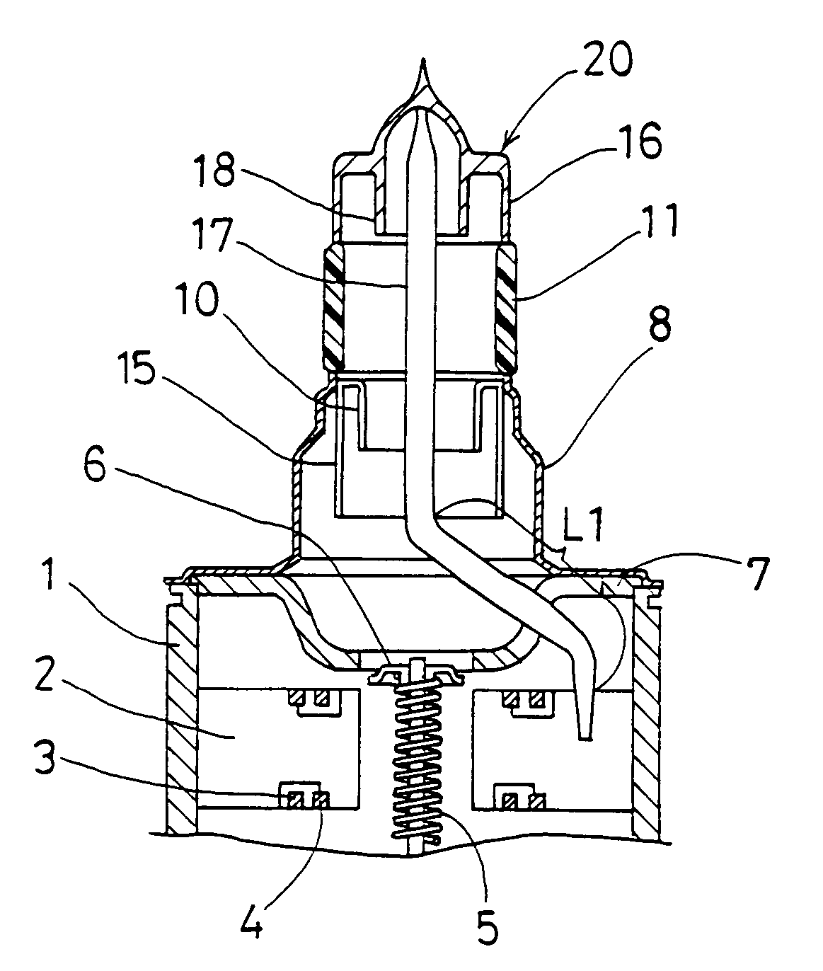
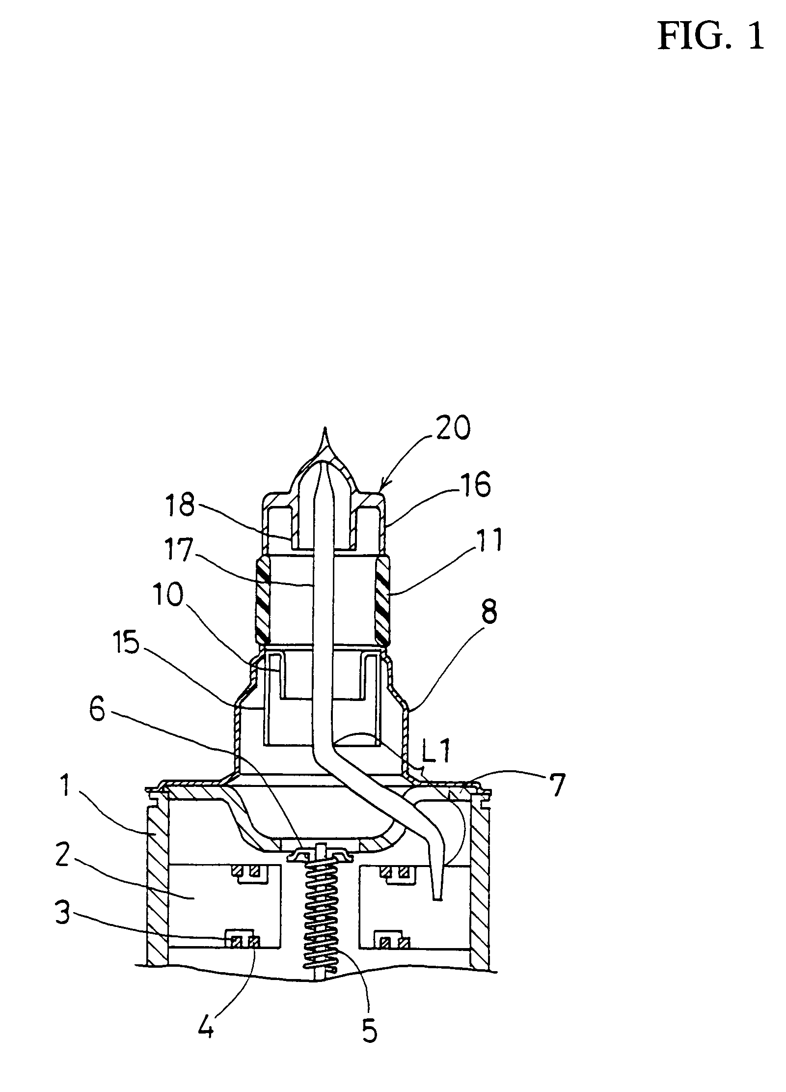
[0061]As shown in FIG. 1, in the magnetron in accordance with the first embodiment, a plurality of plate-formed anode segments 2 are secured to the inner wall of a cylindrical anode cylinder 1, and the anode segments 2 are disposed at equal intervals toward the central axis of the anode cylinder 1. Inside the anode cylinder 1, a cathode 5 is disposed along the central axis thereof in the vertical direction, and each of the upper and lower ends of the cathode 5 is secured to an end hat 6. In FIG. 1, the lower end of the cathode 5 is not shown. The upper and lower ends of the respective anode segments 2 are connected alternately and electrically via a pair of large and small strap rings 3 and 4, respectively. At the upper and lower opening ends of the cylindrical anode cylinder 1, metal cylinders 8 are hermetically sealed via magnetic pole pieces 7.

[0062]Inside the metal cylinder 8 sealed at the opening end of the upper portion (the output side) of the anode cylinder 1, in the upper p...

second embodiment

[0079]As shown in FIG. 5, in the magnetron in accordance with the second embodiment, a third harmonic restraint choke 19 has a large diameter portion 19b on the output portion side (the upper side) and has a small diameter portion 19a on the cathode side (the lower side), thereby being formed into a cylindrical shape having a step.

[0080]In the magnetron in accordance with the second embodiment, its configuration is the same as the configuration of the above-mentioned first embodiment except for the third harmonic restraint choke 19 having the small diameter portion 19a and the large diameter portion 19b. In other words, the magnetron in accordance with the second embodiment is configured so that the electrical length L2 of the antenna lead 17 from the end of the anode segment 2 to which the antenna lead 17 is secured to the end of the third harmonic restraint choke 19 is ½ of the wavelength (λ) of the third harmonic. This electrical length L2 is shown in FIG. 5.

[0081]In the magnetro...


PUM


Abstract

A magnetron is configured so that an antenna lead 17 connected to a desired position of an anode segment 2 passes through a magnetic pole piece 7 and a metal cylinder 8 so as not to make contact therewith and is connected to the output portion of the magnetron, and so that the electrical length L1 of this antenna lead 17 between the opening end of a third harmonic restraint choke 15 and the connection portion of the anode segment 2 is 1/2 of the wavelength (λ) of the third harmonic, thereby restraining the third harmonic and the side bands of the third harmonic.

Description

[0001]This application claims the priority of Japanese patent application No. 2002-222781 filed 0n Jul. 31, 2002.BACKGROUND OF THE INVENTION[0002]The present invention relates to a magnetron for use in microwave ovens and the like, and more particularly to a mechanism for restraining the leakage of harmonic components from the output portion of the magnetron.[0003]Generally, a magnetron for a microwave oven generates a microwave of 2.45 GHz as a fundamental wave. When generating the microwave, the magnetron generates harmonic components having frequencies of integral multiples of the fundamental wave in addition to the fundamental wave, simultaneously. When the harmonic components are radiated from the output portion, just like the fundamental wave, the harmonics are propagated into the microwave oven. Since the wavelengths of the harmonics are short, when they are propagated once into the microwave oven, it is difficult to prevent their leakage to the outside of the microwave oven....

Claims


Application Information

Patent Timeline
IPC IPC(8): H01J25/50H01J23/54H01J23/15H01J23/40H01J23/44H01J25/587
CPCH01J23/54H01J25/587H01J23/15
Inventor ISHII, TAKESHISAITOU, ETSUOYOSHIHARA, MASANORITSUKADA, TOSHIYUKIOHGURI, HIDEKI
Owner PANASONIC CORP
Why Eureka
Try Eureka