Rotation angle detecting device including magnetic member with concave surface

a magnetic member and detecting device technology, applied in galvano-magnetic devices, galvano-magnetic hall-effect devices, instruments, etc., can solve the problems of not being able to the magnetic sensor element cannot detect an accurate rotation angle when a rotary object rotates, so as to prevent detection errors and prevent detection errors

Inactive Publication Date: 2006-12-12
DENSO CORP
View PDF12 Cites 16 Cited by
  • Summary
  • Abstract
  • Description
  • Claims
  • Application Information

AI Technical Summary

Benefits of technology

[0009]The first object is to prevent a detection error by keeping the magnetic flux that passes through the magnetic sensor element constant even if the magnetic sensor element shift

Problems solved by technology

(1) Magnetic leakage is significant at axial ends of the permanent magnets. If the magnetic sensor element shifts in the axial direction or along the center axis of rotation, a predetermined amount of magnetic flux is not supplied to the magnetic sensor element, so that the magnetic sensor element can not detect an accurate rotation angle when a ro

Method used


Image

  • Rotation angle detecting device including magnetic member with concave surface
  • Rotation angle detecting device including magnetic member with concave surface
  • Rotation angle detecting device including magnetic member with concave surface

Examples


first embodiment

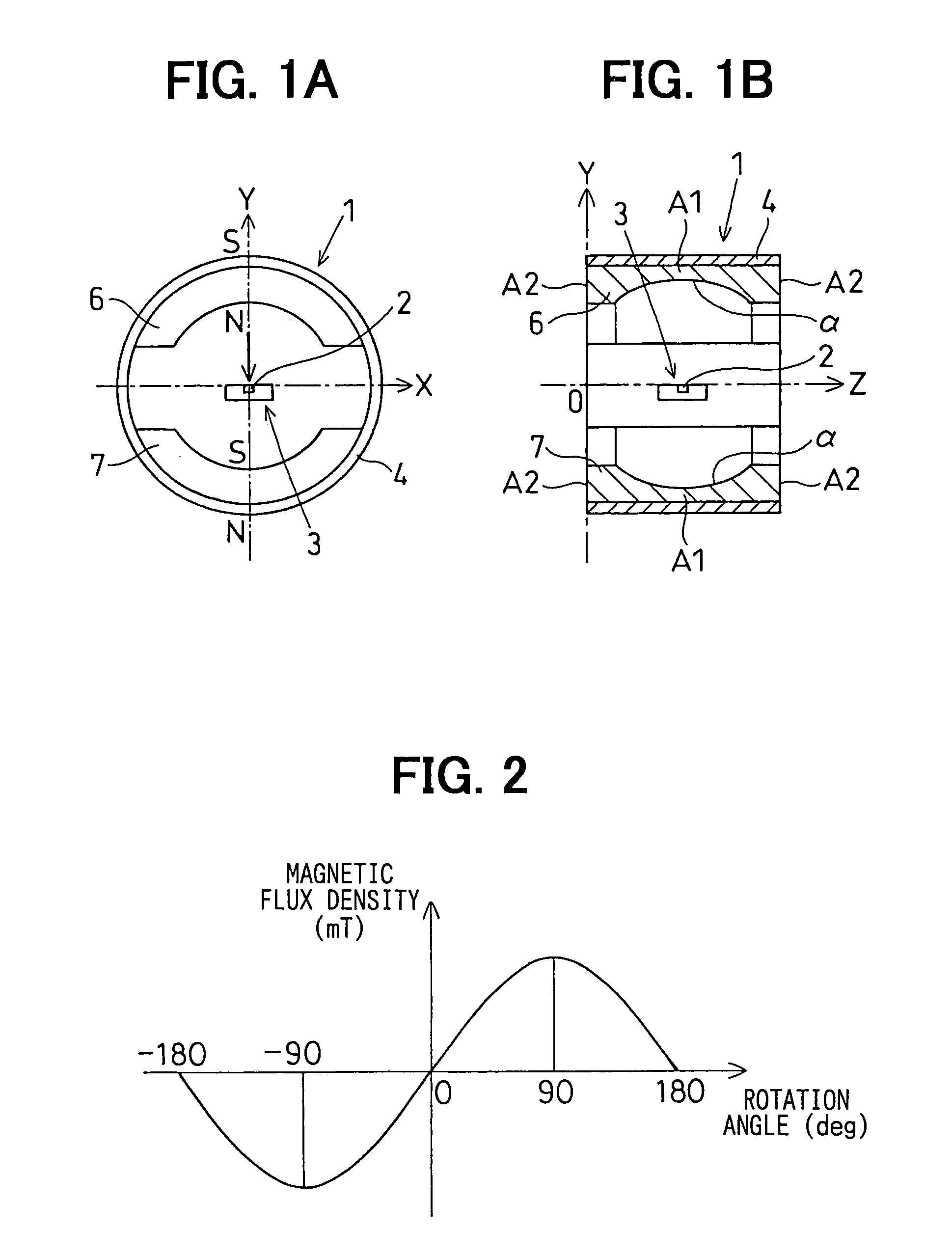
[0043]A rotation angle detecting device according to the invention will be described with reference to FIGS. 1–3.

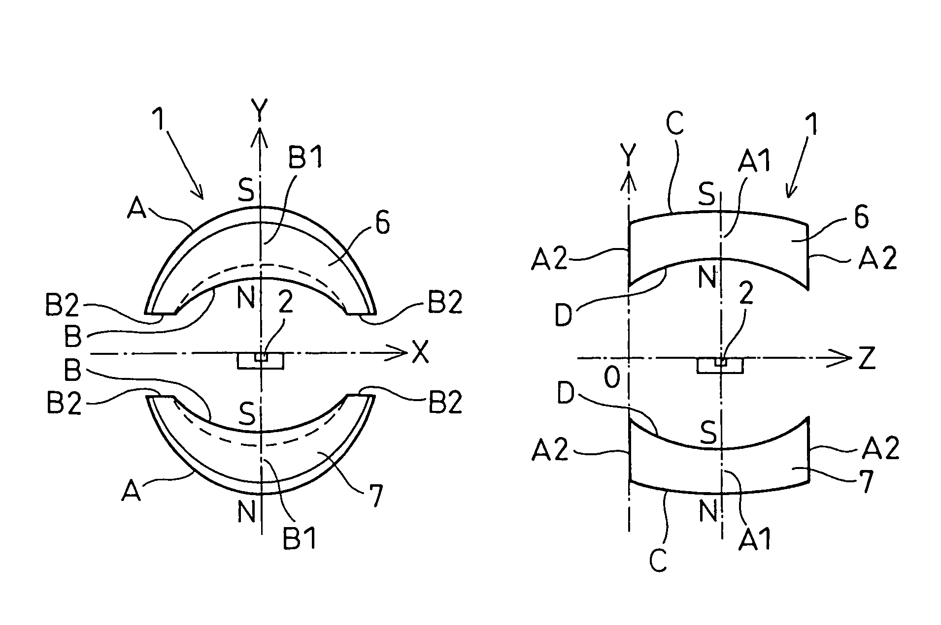
[0044]The rotation angle detecting device according to the first embodiment is to be used for detecting rotation angle of a throttle valve of an internal combustion engine. The rotation angle detecting device includes a rotor 1, a hall IC 3 in which a hall element 2 is integrated.

[0045]The hall IC 3 is supported by a stationary member so that the hall element 2 is positioned on the center axis z of the rotor 1. The hall IC 3 is a well-known type, which includes a signal processing circuit as well as the hall element 2. The hall IC 3 has a magnet sensing surface that provides a signal according to a magnetic flux density in the direction perpendicular to the magnet sensing surface. That is, as shown in FIG. 2, the magnetic flux density sensed by the hall IC 3 becomes maximum when the rotor 1 is positioned as shown in FIG. 1A, and minimum when the rotor 1 rotates 90 degrees...

second embodiment

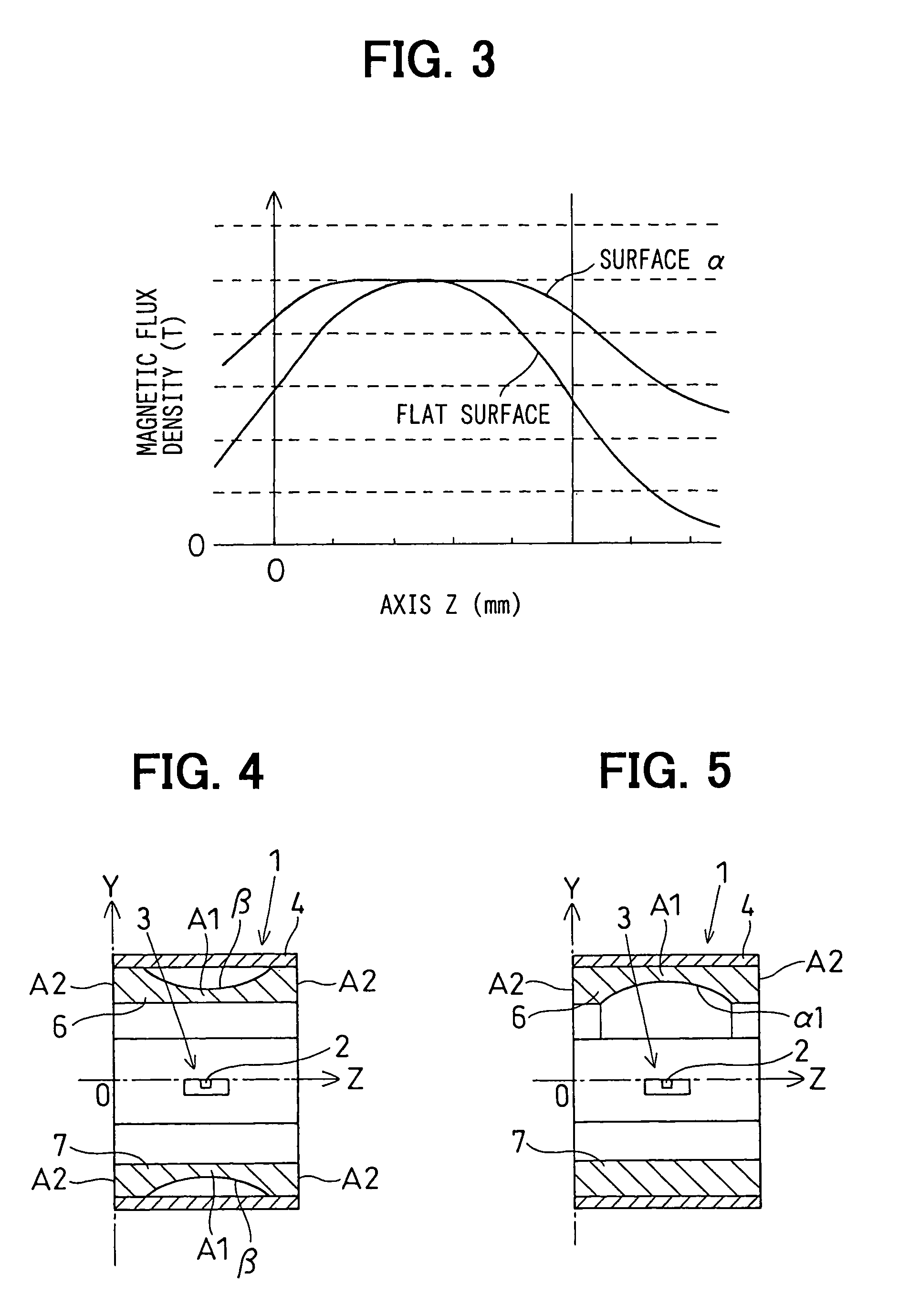
[0048]The rotation angle detecting device 1 has a pair of permanent magnets each of which has a circumferentially extending rut-shaped concavity β at its radially outer surface. Therefore, each of the permanent magnets 6, 7 has a minimum radial thickness at the axially central portion A1 thereof around the hall element 2 in the axial direction z. The concavity β is formed so that the magnetic flux density of the magnetic flux flowing through the magnet sensing surface becomes constant even if the hall element shifts a little in the axial direction z.

third embodiment

[0049]A rotation angle detecting device according to the invention will be described with reference to FIG. 5.

[0050]The rotation angle detecting device 1 according to the third embodiment has a pair of permanent magnets 6, 7. However, one of the permanent magnets has a circumferentially extending rut-shaped concavity α1 at its radially inner surface. Therefore, the permanent magnet 6 has a minimum radial thickness at the axially central portion A1 thereof around the hall element 2 in the axial direction z. The concavity α1 is formed so that the magnetic flux density of the magnetic flux flowing through the magnet sensing surface becomes constant even if the hall element shifts a little in the axial direction z.


PUM


Abstract

A rotation angle detecting device for a rotation object includes a rotor and a pair of permanent magnets and a magnetic detector disposed at the rotation axis of the rotation object. One of the permanent magnets has a circumferentially extending rut-shape concavity around the magnet detector or an axially extending elliptic columnar surface having a central portion thicker than others to make magnetic flux density in the vicinity of said magnetic detector constant in an axial or a diametrical direction.

Description

CROSS REFERENCE TO RELATED APPLICATION[0001]The present application is based on and claims priority from the following Japanese Patent Applications: 2003-96737, filed Mar. 31, 2003; and 2004-28085, filed Feb. 4, 2004; the contents of which are incorporated herein by reference.BACKGROUND OF THE INVENTION[0002]1. Field of the Invention[0003]The present invention relates to a rotation angle detecting device which detects a relative rotation angle between a rotary object and a stationary object. Such a rotation angle detecting device can be used for an engine throttle valve control, a robot arm control and the like.[0004]2. Description of the Related Art[0005]A conventional rotation angle detecting device includes a magnetic sensor element, such as a hall element integrated with an IC chip, and a pair of semi-cylindrical permanent magnets disposed to surround the magnetic sensor element, as shown in JP-B2-3206204, JP-A-Hei 2-122205, JP-A-Hei 2-298815 and JP-A-sho 64-37607. Such a conven...

Claims


Application Information

Patent Timeline
IPC IPC(8): G01B7/30G01B7/00G01D5/14
CPCG01D5/145
Inventor MIZUTANI, AKITOSHIBAN, TAKAO
Owner DENSO CORP
Why Eureka
Try Eureka