
Optical coupling arrangement

Inactive Publication Date: 2006-12-12
RPX CORP
View PDF6 Cites 102 Cited by
  • Summary
  • Abstract
  • Description
  • Claims
  • Application Information

AI Technical Summary

Benefits of technology

[0006]It is an object of the invention to provide an improved manufacturing method, a coupling arrangement and an apparatus for manufacturing the coupling arrangement that allow simplifying the manufacture and enabling mass production without compromising the quality.
[0012]The method and system of the invention provide several advantages. The manufacture of the coupling arrangement comprising a waveguide structure and coupling elements for coupling optical radiation between the waveguide structure and the environment is simplified, and made more rapid and more economical. In addition, the solution makes mass production possible without having to deal with the problems concerning quality.

Problems solved by technology

A conventional optical system comprises macroscopic components placed widely apart from one another, and the size of a particularly complicated optical system may fill even a cubic meter space.
A problem with the optical coupling arrangement based on substrate waveguide is that it is poorly applicable to be utilized industrially, as in order to manufacture a diffractive element the substrate must be etched and metal coated or a holographic pattern must be prepared.
Such a work can only be carried out in a laboratory by hand, which in turn results in the fact that the coupling arrangement becomes very expensive, is slow to manufacture and the quality is poor due to the tolerances associated with the aligning of the parts.
An extensive production to fulfil the needs of telecommunication applications for example is therefore not possible, as mass production is required in industrial applications.

Method used


Image

  • Optical coupling arrangement
  • Optical coupling arrangement
  • Optical coupling arrangement

Examples


Embodiment Construction

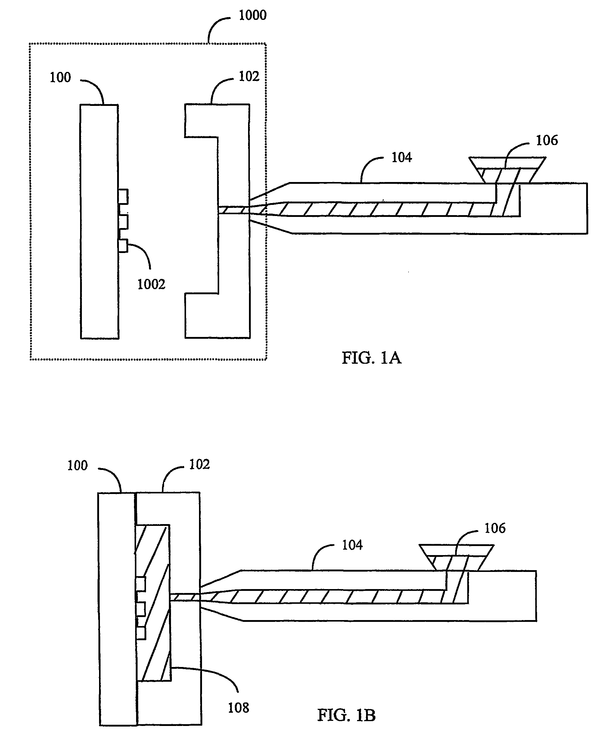
[0025]Several replication processes of polymer material exist, such as injection moulding and hot moulding, without being restricted thereto. FIGS. 1A and 1B show as an example the principle of an injection moulding method. An injection moulding arrangement according to FIG. 1A comprises a mould including a cover 100 and a bottom 102. In addition, the injection moulding arrangement comprises a feed clamp 104 with liquid polymer 106 (or plastic). The cover 100 is provided with a model 1002 for pressing or moulding microstructures, the model 1002 being commonly placed in a separately manufactured pattern plate, which is for instance a printing plate or another plate comprising a diffractive pattern. In FIG. 1B the cover 100 is fastened to the bottom 102 of the mould and liquid polymer mass is pressed or injected into the mould. A part 108 resembling the mould is formed in the mould, and a microstructure shaped according to the model 1002 is pressed onto the surface of the part 108. Mo...


PUM


Abstract

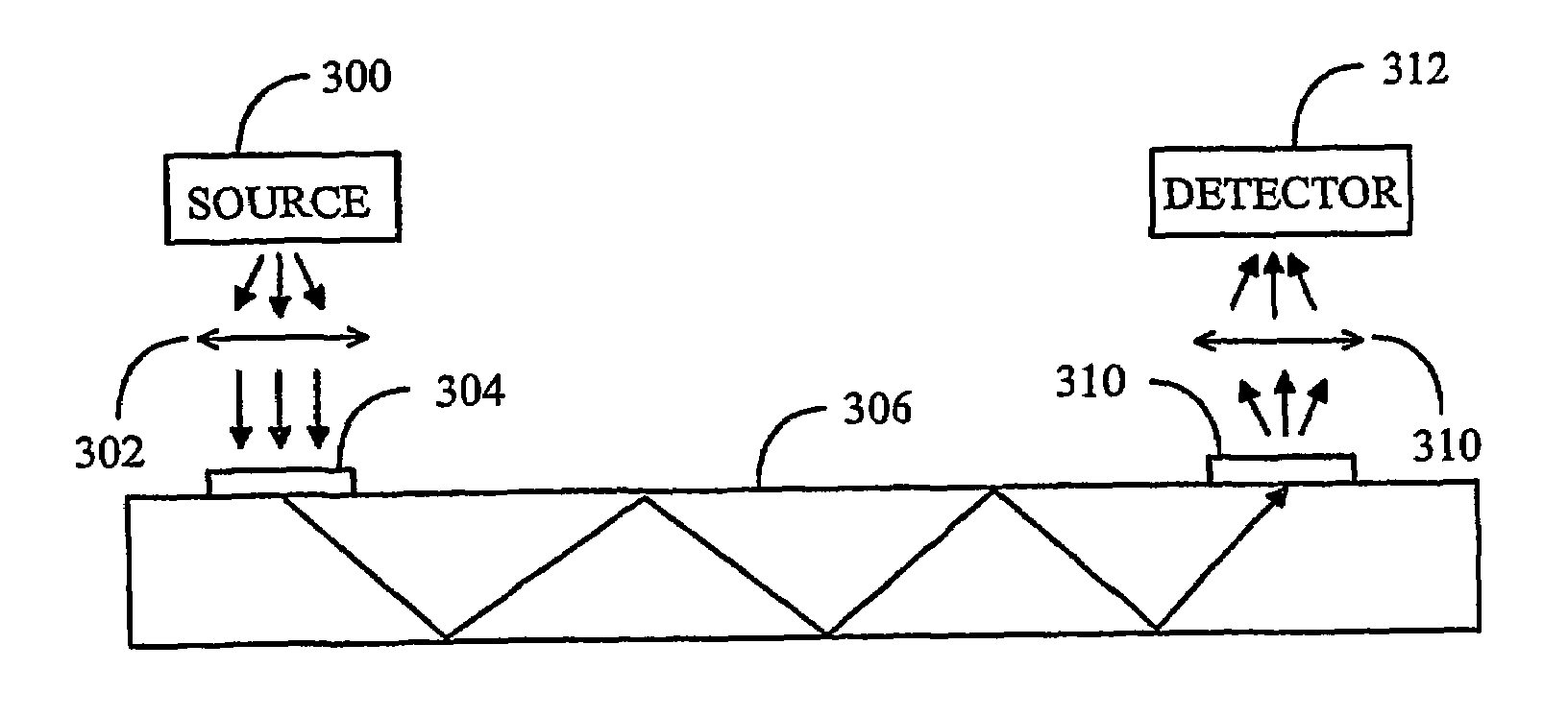
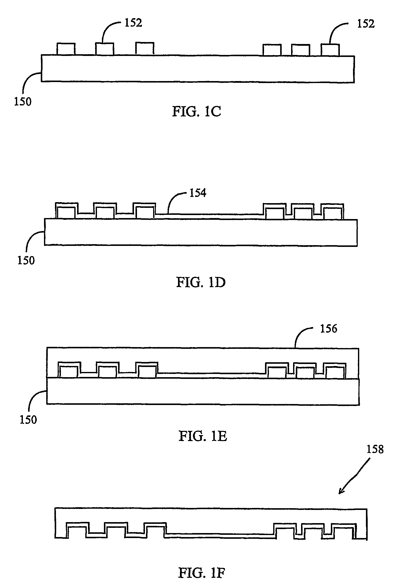
The invention relates to a method and an apparatus for manufacturing an optical coupling arrangement, and a specific coupling arrangement. A substrate waveguide (306) and at least one coupling element (304, 306) in the coupling arrangement are made of polymer material in the same replication process at the same time. At least one diffractive coupling element (304, 306) is then formed in the polymer material by placing the polymer material against a replication mould, which comprises a surface profile model of at least one diffractive coupling element (304, 306) that is patterned into the replication mould by means of micro lithography.

Description

FIELD OF THE INVENTION[0001]The invention relates to an optical coupling arrangement based on a waveguide and on the use of a diffractive coupling element for coupling optical radiation to or from the waveguide.BACKGROUND OF THE INVENTION[0002]Optics plays an important part in for instance lighting technology, medicine, industrial measuring and monitoring applications and in telecommunications technology. A conventional optical system comprises macroscopic components placed widely apart from one another, and the size of a particularly complicated optical system may fill even a cubic meter space. In integrated optics, the aim is to combine optoelectro-mechanical structures in order to reduce the size using waveguide optics, packed optics or plane integrated optics.[0003]Integrated microtechnology often employs diffractive optics, the components thereof comprising microstructures for manipulating optical radiation as desired. A diffractive component is used for example as a lens, a be...

Claims


Application Information

Patent Timeline
IPC IPC(8): G02B6/34G02B6/122G02B6/42G02B6/43
CPCG02B6/1221G02B6/34G02B6/42G02B6/43
Inventor PARIKKA, MARKOTURUNEN, JARI
Owner RPX CORP
Learn More