System for flexible embedded Boundary Scan testing

a flexible, boundary scan technology, applied in the direction of instruments, computing, measurement devices, etc., can solve the problems of time-consuming and laborious process of altering such programs, unable to determine the functionality and continuity of electronic assemblies, and limited current methods

Active Publication Date: 2006-12-12
LUCENT TECH INC
View PDF13 Cites 22 Cited by
  • Summary
  • Abstract
  • Description
  • Claims
  • Application Information

AI Technical Summary

Problems solved by technology

As integrated circuit packaging technology has decreased in size, the ability to determine functionality and continuity of electronic assemblies has become increasingly more difficult.
However, current methods are limited in that the tests are specific to the connectivity of the existing board level integrated circuit configuration.
As has been found, altering such programs is a time- and labor-intensive process as the new functions must be tested to insure they work properly and existing functions must be re-tested to establish that their operation was not altered by the new changes.
However, this method is limited as once a start address is determined the testing continues until the end of the scan vectors for the selected scan block vector suite is reached.
Furthermore, the prior art only provides for rudimentary conditional flow control in the order of jumps and if-then conditionals.
Thus the embedded BIST approach does not lend itself well to reliability testing, such as Environmental Stress Test (EST), where a sequence of operations must be performed repetitively for a specific period of time or when an error condition is detected.
The prior art is also limited in scope in what test functions can be performed as, typically, there is a single static vector test format available to perform Boundary Scan operations.
Furthermore, the prior art fails to provide adequate support for product testing over the entire product life cycle as part of a Built-In test strategy.

Method used


Image

  • System for flexible embedded Boundary Scan testing
  • System for flexible embedded Boundary Scan testing
  • System for flexible embedded Boundary Scan testing

Examples


Embodiment Construction

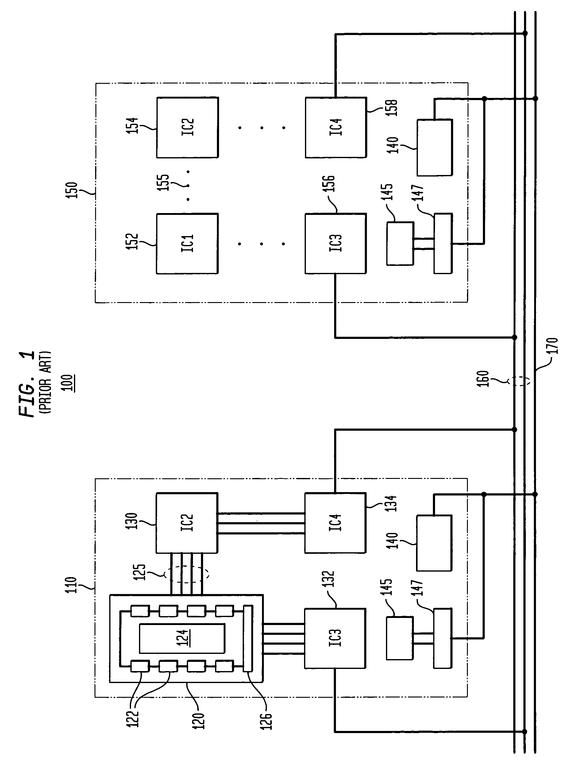
[0022]FIG. 1 illustrates a conventional Boundary Scan test system configuration 100 including details of both board and integrated circuit tests. More specifically, system 100 is composed of boards 110 and 150 communicating via bus 160. Board 110 includes a plurality of integrated circuits 120, 130, 132 and 134, which are in communication via interconnection tracks 125, for example. Board 150, similarly, includes a plurality of integrated circuits 152, 154, 156, and 158, in communication via interconnection tracks 155. Integrated circuit 120 illustrates a conventional Boundary Scan configuration wherein core logic 124 is surrounded on the boundary of integrated circuit 120 with programmable cells 122. Typically, the programmable cells 122 are “daisy-chained” together to allow data to be passed from one cell to the next. Test Access Port (TAP) controller 126 provides a control means to route serial input signals, i.e., Test Data In (TDI), for setting and clearing individual cells 122...


PUM


Abstract

A flexible Boundary Scan test system is disclosed. The system includes an interpreter module operable to execute a program element selected from a plurality of program elements that include at least one instruction type having an interface to identify and execute selected functions wherein each of the selected functions has associated therewith at least one data information item. In one aspect of the invention, selected ones of the functions are composed of a plurality of functions. In another aspect of the invention, the instruction includes parameters and adornments for determining the selected function execution.

Description

FIELD OF INVENTION[0001]The present invention is related to electronic printed circuit board and system assembly testing and more specifically to provide a flexible method for implementing tests for embedded Boundary Scan testing.BACKGROUND OF THE RELATED ART[0002]As integrated circuit packaging technology has decreased in size, the ability to determine functionality and continuity of electronic assemblies has become increasingly more difficult. Integrated circuit boundary scan features are well known in the art and is typically used in Personal-Computer (PC) based tests and in Automatic Test Equipment (ATE) testing used in manufacturing. An example of Boundary-Scan testing is disclosed in U.S. Pat. No. 6,594,802, entitled “Method and Apparatus for Providing Optimized Access to Circuits for Debug, Programming and Test, issued Jul. 15, 2003 to Ricchetti, et al.[0003]An advantage of Boundary Scan testing is that it is structural in nature and is amenable to explicit coverage metrics. ...

Claims


Application Information

Patent Timeline
Patent Type & Authority Patents(United States)
IPC IPC(8): G01R31/28G06F17/50G01R31/3185
CPCG01R31/318544G01R31/318555
Inventor VAN TREUREN, BRADFORD G.MIRANDA, JOSE M.WHEATLEY, PAUL J.
Owner LUCENT TECH INC
Why Eureka
Try Eureka