Capacitive micromachined acoustic transducer

a micromachined acoustic transducer and micromachine technology, applied in the direction of semiconductor electrostatic transducers, instruments, fluid pressure measurement, etc., can solve the problems of introducing frequency-dependent stiffness and loss, achieving a large dynamic range and high sensitivity, and achieving stable and reliable operation. stable and reliable, wide bandwidth

Active Publication Date: 2006-12-26
NEOMEMS TECH INC WUXI CHINA
View PDF16 Cites 37 Cited by
  • Summary
  • Abstract
  • Description
  • Claims
  • Application Information

AI Technical Summary

Benefits of technology

[0009]It is another object of the present invention to provide a micromachined acoustic transducer that has wide bandwidth and high sensitivity, yet its operation is stable and reliable.
[0010]It is a further object of the present invention to provide a micromachined acoustic transducer that features the mechanism to suppress the unwanted rolling noise at audio band.
[0011]It is another object of the present invention to provide a micromachined acoustic transducer that has the shallowly corrugated structures that further provide relatively stable sensitivity.

Problems solved by technology

However, the reduced dimensions of the air gap magnify the effects of squeeze-film damping, introducing frequency-dependent stiffness and loss.
This creates undesirable variations in the mechanical response with acoustic frequency.
Furthermore, achieving a large dynamic range and a high sensitivity can be conflicting goals, since large sound pressures may cause the membrane to collapse under its voltage bias.
This traditional approach suffers from low sensitivity, especially at low frequencies.
For most very thin diaphragms, however, large residual stress can lead to undesirable effects such as low and irreproducible performances, if the processes cannot accurately be controlled.
Unfortunately, in this case, the freely suspended membrane will have unstable sensitivity and unwanted lateral movement, resulting in the signal spew and posing the reliability issues.

Method used


Image

  • Capacitive micromachined acoustic transducer
  • Capacitive micromachined acoustic transducer
  • Capacitive micromachined acoustic transducer

Examples


Embodiment Construction

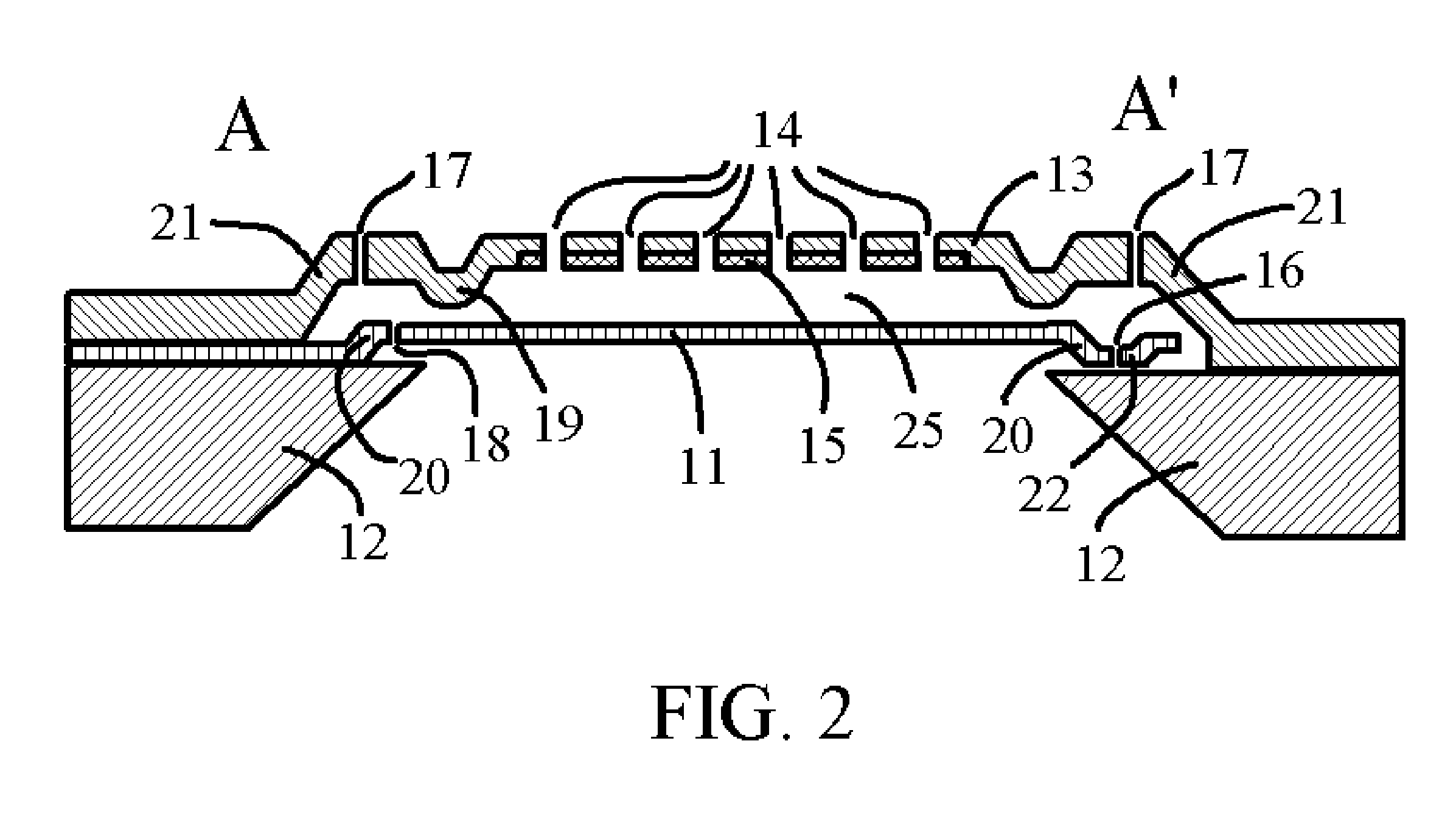
[0021]We approach the problem of making a good and practical micromachined acoustic transducer from a different perspective. Our stress releasing technique is to form corrugations in the membrane. The corrugated membrane is capable of releasing the built-in stress during the processing, thereby increasing the mechanical sensitivity of the membrane and reducing the irreproducibility. Compared with the conventional flat diaphragm, the shallowly corrugated membrane has an increased sensitivity, especially for a high residual stress level.

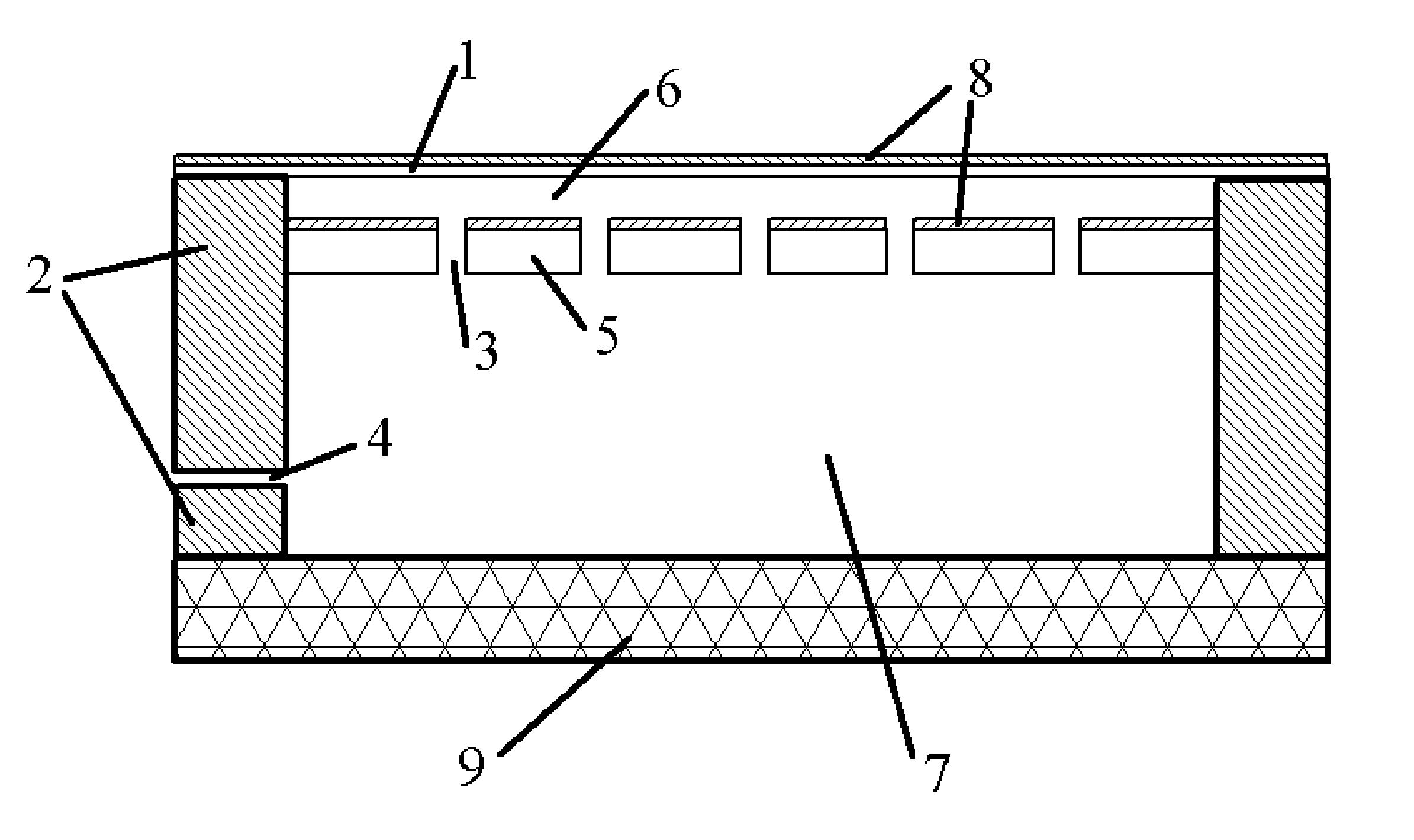
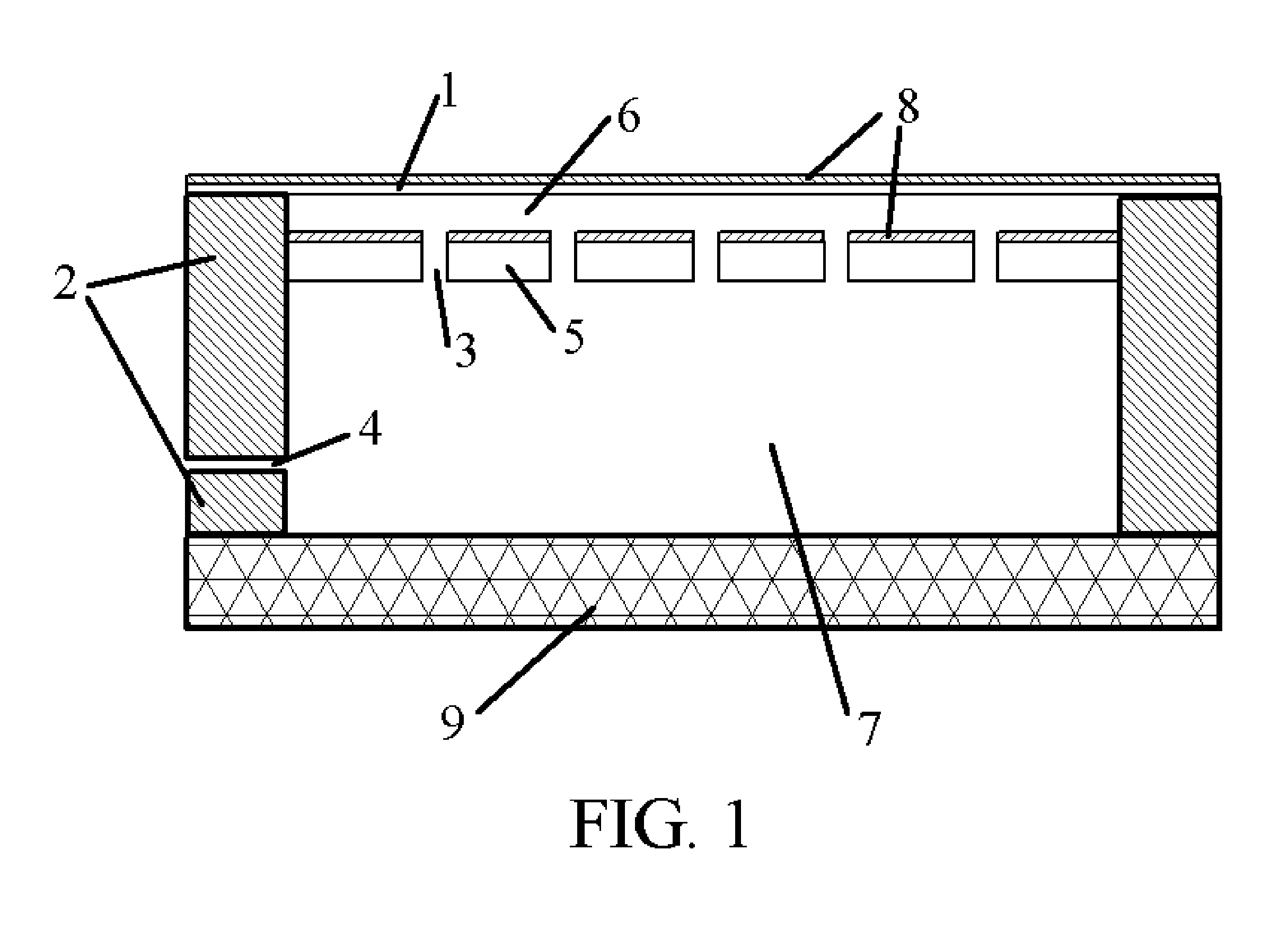
[0022]Referring now to FIG. 2, this is a cross-sectional view of a micromachined acoustic transducer along the line A–A′ in FIG. 4 according to the preferred embodiment of the present invention. A shallowly corrugated membrane 11 is anchored at one end on the substrate 12, and loose at the other end. The built-in stress in the membrane 11 is released through corrugation 20 on the membrane 11. The built-in stress in membrane 11 is further release throug...


PUM


Abstract

A micromachined capacitive acoustic transducer including an electrode formed by a perforated plate and another electrode formed by a shallowly corrugated membrane anchored at one or more positions on the substrate which also supports the said perforated plate is described. Also disclosed includes: a fixed perforated plate; a movable shallowly corrugated membrane having holes to form acoustic filter to a certain frequency or a range of frequencies spaced from the perforated plate that is anchored in one or more location but loose at other locations; a support structure in the perforated plate maintaining the minimum separation between the membrane and the perforated plate near the perimeter.

Description

CROSS REFERENCE TO RELATED APPLICATION[0001]U.S. Pat. No.: 5,146,435; 5,452,268; 5,619,476; 5,870,351; 5,894,452; 6,493,288; 6,535,460; 6,847,090; 6,870,937.BACKGROUND OF THE INVENTION[0002]The batch processing of micromachining has led to the emergence of capacitive micromachined transducers. These transducers offer a larger set of parameters for optimization of performance as well as ease of fabrication and electronic integration. The fabrication and operation of micromachined transducers have been described in many publications and patents. For example, U.S. Pat. Nos. 5,619,476, 5,870,351, 5,894,452 and 6,493,288 describe the fabrication of capacitive-type ultrasonic transducers. U.S. Pat. Nos. 5,146,435; 5,452,268, and 6,870,937 also describe micromachined capacitive transducers that are mainly used in the audio range for sound pickups. In most structures, the movable diaphragm of a micromachined transducer is either supported by a substrate or insulative supports such as silico...

Claims


Application Information

Patent Timeline
Patent Type & Authority Patents(United States)
IPC IPC(8): H04R25/00
CPCB81B3/0072H04R19/005B81B2201/0257B81B2203/0127
Inventor WANG, YUNLONG
Owner NEOMEMS TECH INC WUXI CHINA
Why Eureka
Try Eureka