Check patentability & draft patents in minutes with Patsnap Eureka AI!

Seal assembly

a technology of sealing elements and components, applied in the direction of machines/engines, liquid fuel engines, light and heating apparatus, etc., can solve the problems of reducing the ability of other materials to withstand high exposure to high stress, reducing the ability of resilient sealing elements to withstand high stress, and reducing the ability of high stress

Inactive Publication Date: 2006-12-26
ANSALDO ENERGIA SWITZERLAND AG
View PDF18 Cites 45 Cited by
  • Summary
  • Abstract
  • Description
  • Claims
  • Application Information

AI Technical Summary

Benefits of technology

The laminated structure significantly reduces heat flux and cooling air requirements, maintaining the seal's resilience and flexibility, while minimizing stress relaxation and creep, thus enhancing the efficiency and stability of the gas turbine's combustor system.

Problems solved by technology

Highly stressed metals are subject to severe stress relaxation at high temperatures, rendering them useless as resilient sealing elements under such conditions.
Even the so called nickel based super alloys such as Inconel 718 and other materials show little ability to withstand exposure to high temperatures beyond 700° C. in a stressed condition without suffering severe stress relaxation and / or creep.
This use of cooling reduces the efficiency of the gas turbine and can impair flame stability.

Method used


Image

  • Seal assembly
  • Seal assembly
  • Seal assembly

Examples


second embodiment

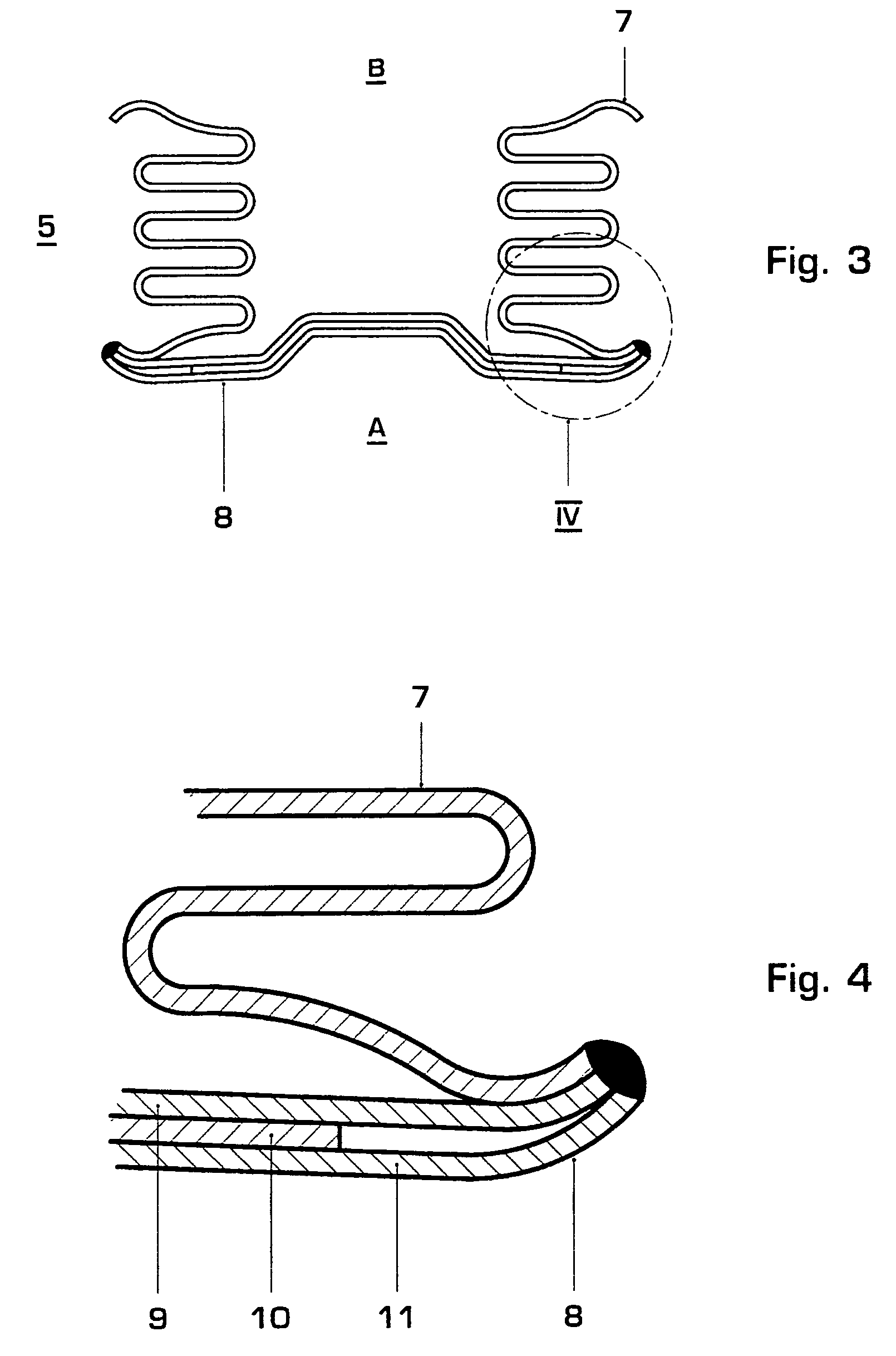
[0035]FIG. 5 illustrates an inventive seal assembly which is consists of a laminated connector plate 8 according to the present invention. As seen in FIG. 5, the connector plate 8 consists of three different layers with layer 9 of a base material, a layer 10 of a thermal insulating material, and a layer 11 of a base material or made of an oxide resistant material. The connector plate 8 is bent around and welded to the two sides of an E-seal 12. The E-seal 12 consists as well of Inconel 718. The E-seal 12 can be provided with or without cooling holes 13 for the flow of cooling air.

third embodiment

[0036]FIG. 6 shows an inventive seal assembly 5. It consists of two layers: an inner and an outer layer of E-seals 12 between which a layer 10 of thermal insulating material is positioned.

[0037]While our invention has been described by an example, it is apparent that other forms could be adopted by one skilled in the art. Accordingly, the scope of our invention is to be limited only by the attached claims.


PUM


Abstract

It is disclosed a seal assembly (5) which comprises a layered structure. It consists of a first layer (9, 12) of a base material, a second layer (10) of thermal insulating material on top of the base material and a third layer (11, 12) of base material or an oxide resistant material on top of the second layer (10) of thermal insulation. The inventive seal assembly (5) described herein can be arranged between combustor liner segments (2).

Description

BACKGROUND OF THE INVENTION[0001]1. Field of the Invention[0002]The invention relates to a seal assembly having a laminated structure.[0003]2. Brief Description of the Related Art[0004]Modern large industrial gas turbines have a shielded combustor such as known from US-B1-6,450,762. Due to the ever greater need for efficiency and combustor stability, the arrangement requires primary to secondary air system seals to be fitted. Driven by the work on known combustor systems, the seals are exposed to ever-higher temperatures, extending to a temperature up to 1500° C. on the hot gas side. It is this thermal exposure that drives the need to define a seal assembly that can live with these temperatures while remaining resilient and responsive to system movement. Highly stressed metals are subject to severe stress relaxation at high temperatures, rendering them useless as resilient sealing elements under such conditions. Even the so called nickel based super alloys such as Inconel 718 and ot...

Claims


Application Information

Patent Timeline
Patent Type & Authority Patents(United States)
IPC IPC(8): F16J15/08F01D11/00F23R3/00
CPCF01D11/005F16J15/0887F23R3/002F23M2900/05004F23M2900/05005F23R2900/00012
Inventor AMOS, PETER G.MCCOLVIN, GORDONMORE, D. GREGORY
Owner ANSALDO ENERGIA SWITZERLAND AG
Features
  • R&D
  • Intellectual Property
  • Life Sciences
  • Materials
  • Tech Scout
  • Unparalleled Data Quality
  • Higher Quality Content
  • 60% Fewer Hallucinations
Learn More