
Board connecting connector and method for producing the same

a technology of connecting connectors and connectors, which is applied in the direction of connection contact member materials, fixed connections, coupling devices, etc., can solve the problems of poor manufacturability, poor formability, and electrical shielding of signal terminals, so as to improve formability and manufacturability, reduce assembly man-hours, and reduce production costs

Inactive Publication Date: 2006-12-26
MOLEX INC
View PDF3 Cites 45 Cited by
  • Summary
  • Abstract
  • Description
  • Claims
  • Application Information

AI Technical Summary

Benefits of technology

[0007]It is an object of the present invention to solve the problem of the shield in a connector to thereby prevent the generation of cross-talk or the like and, further, to achieve, by forming the connector components as units, a reduction in assembly man-hour and an improvement in formability and manufacturability to thereby achieve an overall reduction in production cost.

Problems solved by technology

The first problem relates to the electromagnetic shielding of the signal terminals.
The second problem is related to the manufacturability and production cost of the receptacle connector.
As a result, it is necessary to perform the contact-forcing-in process and the shield-plate-forcing-in process for every 25 times each, that is, for every 50 times in total, resulting in poor manufacturability and high production cost.
Needless to say, the problem of the shield described above, is not solved in this case, either.
However, as the number of poles increases, the number of parts including shield plates, increases steeply, resulting in an increase in production cost due to the increase in assembly man-hour and the complication of the assembly operation.
Further, the larger the number of poles is, the more complicated and the more delicate the housing becomes, which leads to a problem related to formability and a problem related to the manufacturability of the mold.

Method used


Image

  • Board connecting connector and method for producing the same
  • Board connecting connector and method for producing the same
  • Board connecting connector and method for producing the same

Examples


Embodiment Construction

[0046]In this embodiment, the present invention is applied to a backplane type connector for electrically connecting boards, which are connected in a so-called right-angle connection, in which the surfaces of the boards cross each other at right angles. This backplane type connector comprises, as shown in FIG. 3, a receptacle connector 10 mounted on the surface of vertical board K1 and a plug connector 20 mounted on the surface of a daughter board K2.

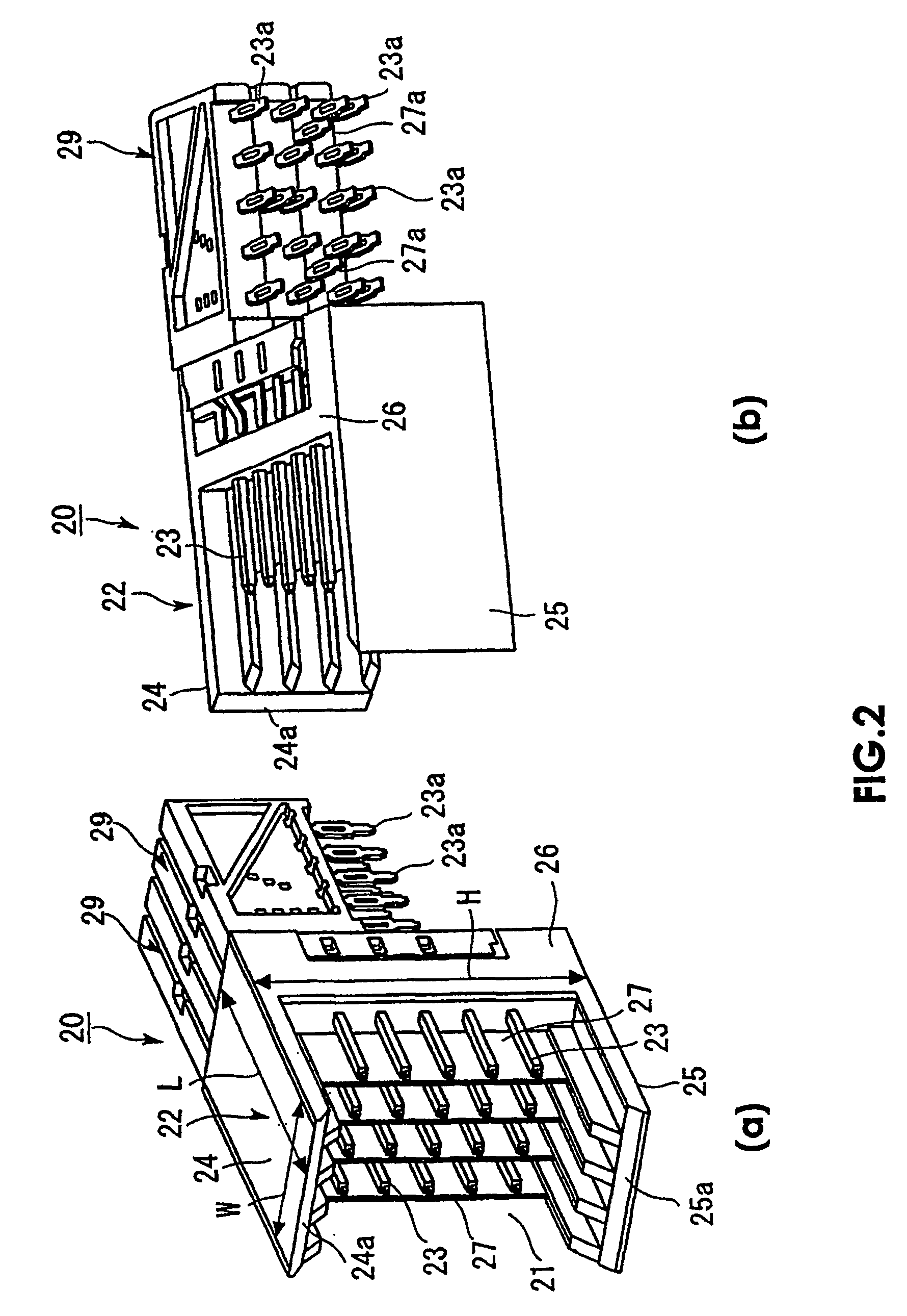
[0047]As shown in FIG. 2, the plug connector 20 is provided with a housing 22 having an opening 21 into which the receptacle connector 10 is to be inserted, and a plurality of pin terminals 23 arranged in a lattice-like fashion with respect to the housing 22. The housing 22 is of a C-shaped configuration in a side view and has a top plate 24, a bottom plate 25, and a back plate 26. The housing 22 is formed such that its width W is smaller than its height H or length L. For convenience in representation of the drawings, the pin terminals...


PUM


Abstract

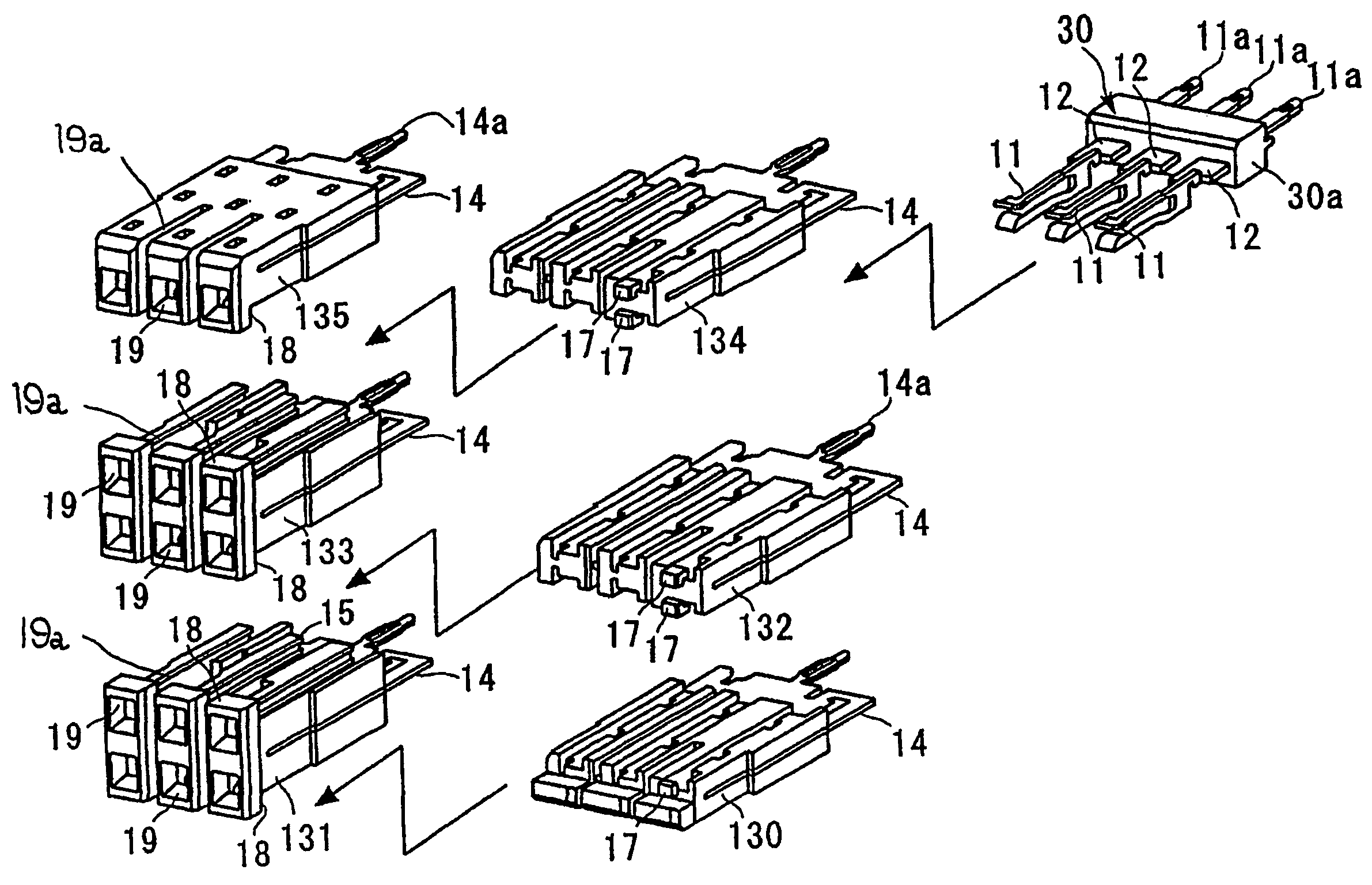
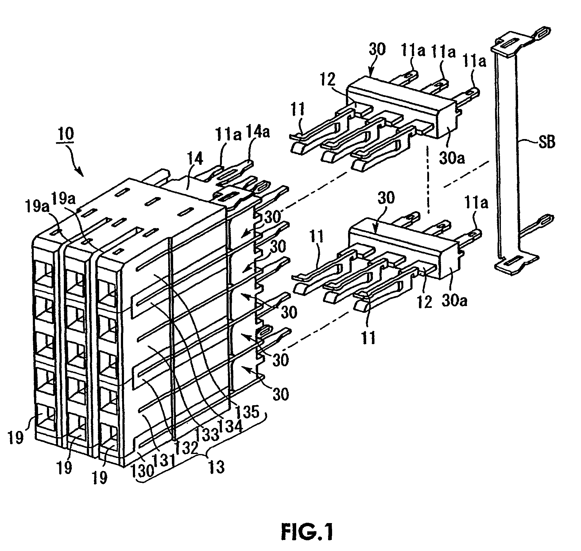
A plug connector is provided with a housing into which the receptacle connector is to be inserted, and a plurality of pin terminals arranged in the housing. The receptacle connector is provided with a plurality of contacts having contact members to be brought into contact with the pin terminals, and a housing holding the contacts. In the plug connector, a plurality of vertical shield plates are provided between the pin terminals. In the receptacle connector, a plurality of horizontal shield plates are provided so as to intersect the vertical shield plates in a cross-like manner. Provided in the housing and the horizontal shield plates of the receptacle connector are slits for allowing insertion of the vertical shield plates. The housing of the plug connector is provided with terminal unit mounting passage for the unit terminals and vertical shield mounting passage for the vertical shield plates.

Description

BACKGROUND OF THE INVENTION[0001]The present invention relates to a backplane type connector for connecting circuit boards electrically to each other, and to a method of producing the same.[0002]Board-to-board connectors are widely used for connecting circuit boards to each other in order to increase the density of circuits or realizing a spatial arrangement of multiple circuit boards. These type of connectors generally include receptacle and plug connectors. The receptacle connector is mounted on a vertical circuit board, while the plug connector is mounted on a daughterboard. It is common for the surfaces of the daughterboards to be perpendicular to the surface of the backplane board, when the two connectors being mated together. Examples of the backplane type connector are disclosed in Japanese Patent Publication A-H06-013133 and U.S. Pat. No. 4,655,518[0003]Recently, these backplane connectors have included multiple pin connectors in which the number of terminal pins ranges from...

Claims


Application Information

Patent Timeline
IPC IPC(8): H01R13/648H01R12/52H01R12/72H01R13/514H01R13/6471H01R13/658H01R13/6586H01R24/00H01R43/00H01R43/18H01R107/00
CPCH01R13/65807H01R13/6471H01R13/6586H01R12/52H01R12/727
Inventor MIZUMURA, AKINORINODA, ATSUHITO
Owner MOLEX INC
Learn More