Video display device with spatial light modulator

a technology of video display device and light modulator, which is applied in the direction of picture reproducers using projection devices, static indicating devices, instruments, etc., can solve the problems of difficult to see clearly, and difficult to correct the color reproductivity of a color having high excitation purity, etc., to enhance the brightness of an image, improve the effect of color reproductivity and avoid complicated circuits

Active Publication Date: 2006-12-26
SHARP NEC DISPLAY SOLUTIONS LTD
View PDF26 Cites 16 Cited by
  • Summary
  • Abstract
  • Description
  • Claims
  • Application Information

AI Technical Summary

Benefits of technology

[0030]In view of the above, it is an object of the present invention to provide a video display device to display a video by modulating light fed from each of light sources for each of three primary colors (R, G, and B) which is capable of providing excellent color reproductivity even when a light source is used in which chromaticity coordinates of each of its three primary colors (R, G, and B) are different from those designated by specifications of colorimetry by which a video signal is defined. It is another object of the present invention to provide a video display device being capable of adjusting color reproductivity according to specifications of colorimetry by which a video signal is defined, It is still another object of the present invention to provide a video display device to display a video by switching, in terms of time, red color light, green color light, and blue color light which is capable of enhancing brightness of an image by additionally applying white color light without causing complicated circuits.

Problems solved by technology

However, in terms of the brightness, if a screen is not sufficiently bright in a viewing environment, the image is difficult to see clearly.
However, since a light emitting principle of a semiconductor light emitting device is different from that of a CRT, it is difficult to make chromaticity coordinates of each of the three primary colors be exactly the same as designated by specifications in the ITU-R Rec.
However, though this method can make tint the same regarding a white point, it is difficult to correct color reproductivity of a color having high excitation purity, that is, a vivid color.
Thus, the conventional video display device employing the semiconductor light emitting device has a problem in that its color reproductivity is not sufficient.
Furthermore, the conventional color-sequence-type video display device has also a problem in that, in addition to a period for applying each of R, G, and B color light, an additional period for applying W color light is prepared separately.
However, control on a spatial light modulator using a video signal for a white color during a period of applying W color light is required, which causes complicated circuits and impairs high-speed operations.

Method used


Image

  • Video display device with spatial light modulator
  • Video display device with spatial light modulator
  • Video display device with spatial light modulator

Examples


first embodiment

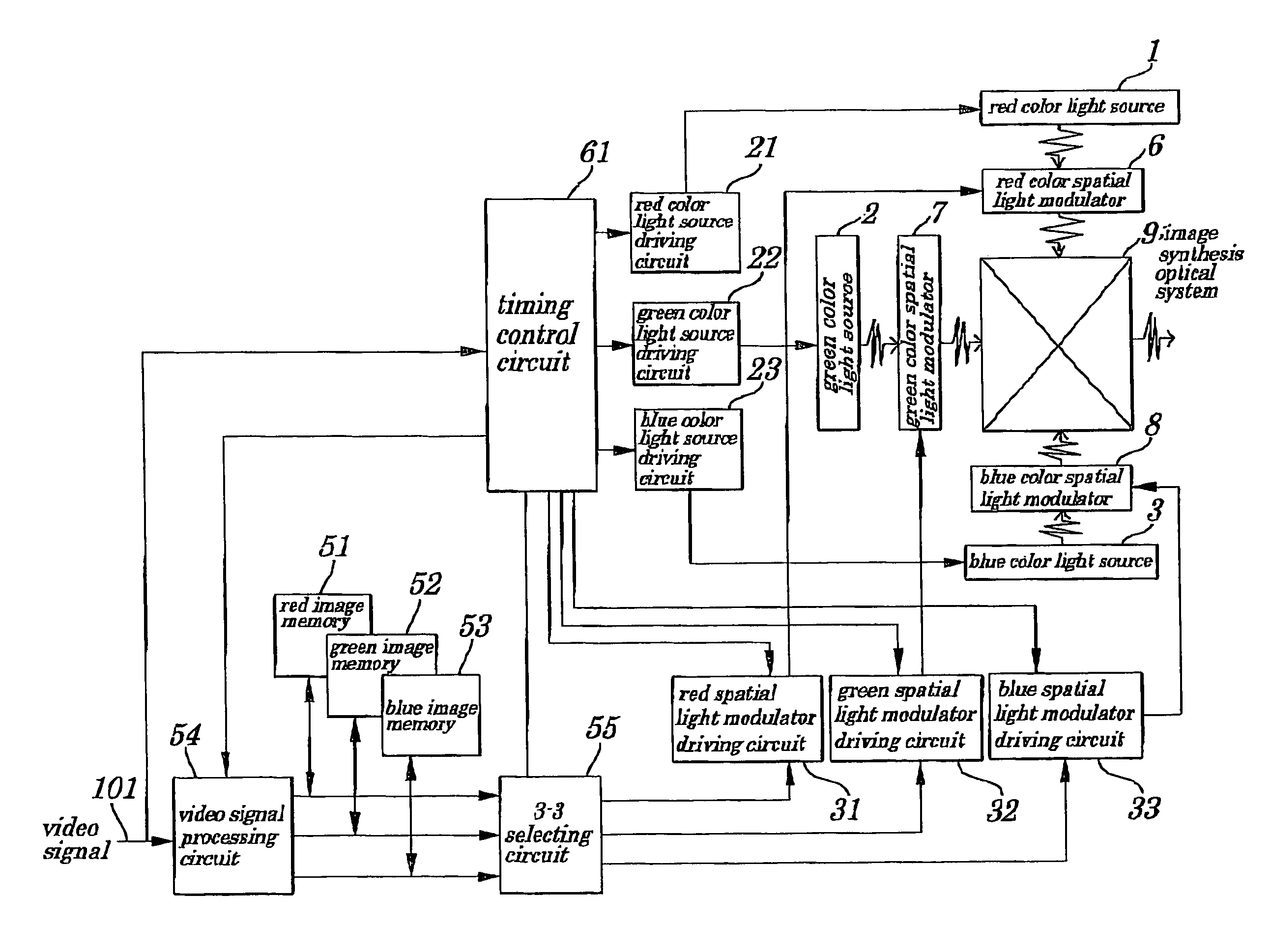
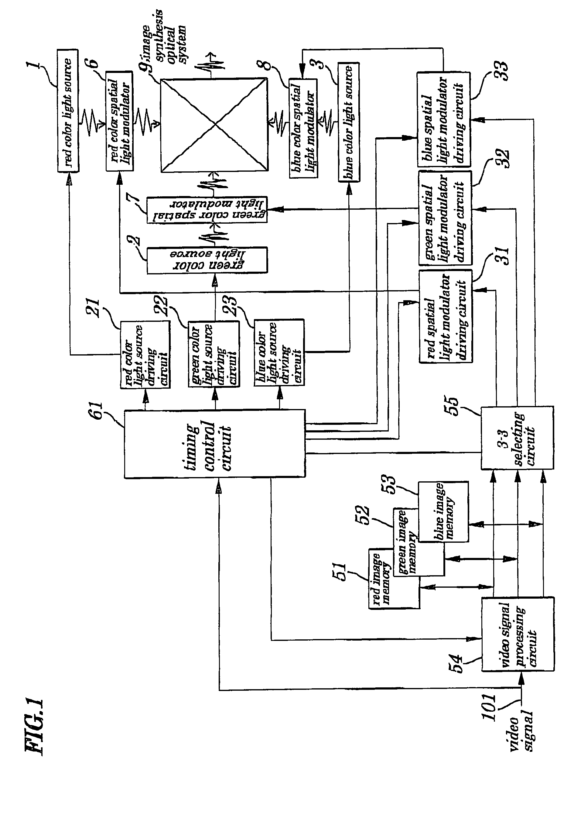
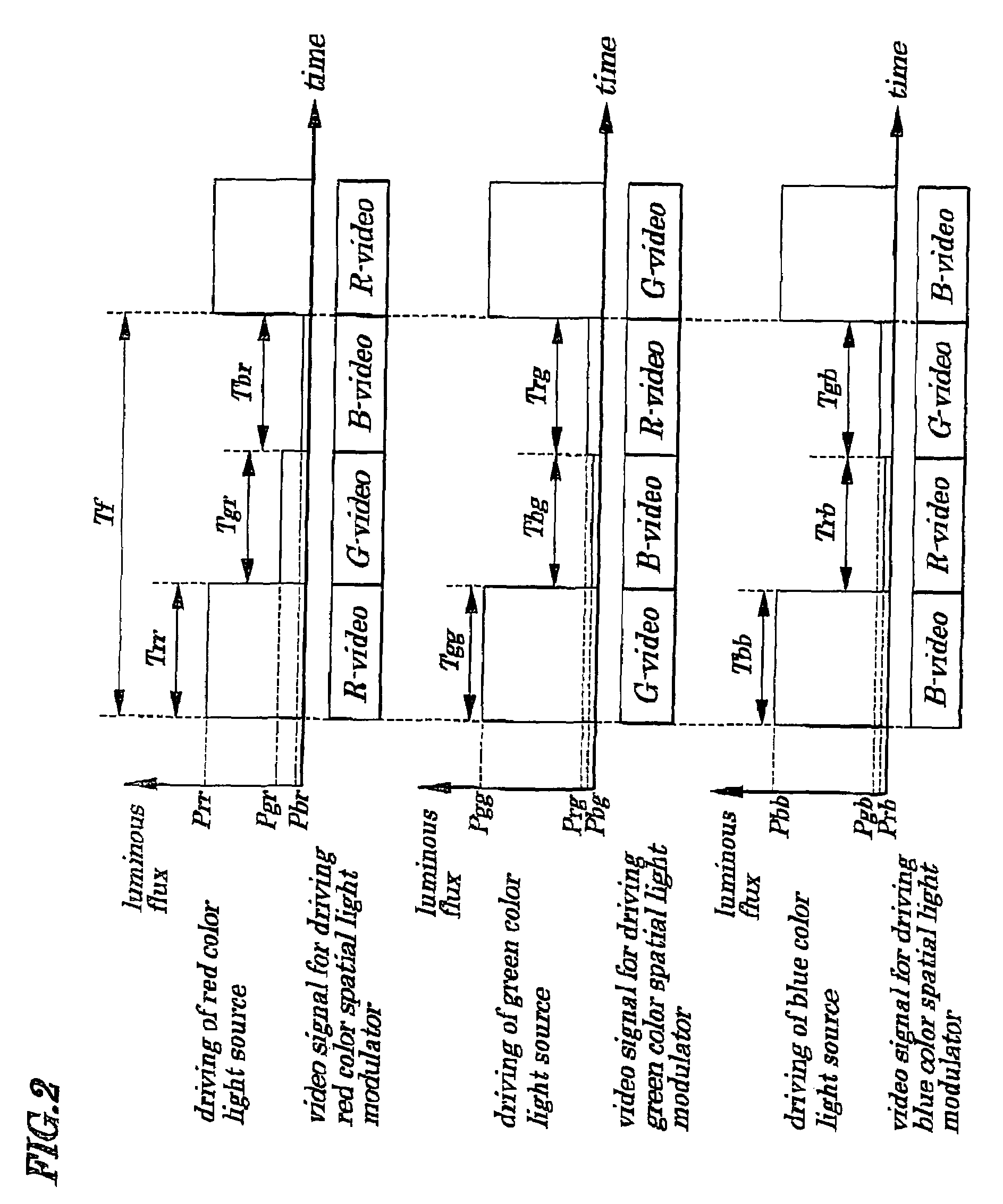
[0111]FIG. 1 is a schematic block diagram showing configurations of a video display device according to a first embodiment of the present invention. FIG. 2 is a timing chart showing a method for controlling a light source for each color employed in the video display device of the first embodiment. FIG. 3 is also a timing chart showing another method for controlling the light source for each color employed in the video display device of the first embodiment.

[0112]The video display device of the first embodiment, as shown in FIG. 1, chiefly includes a red color light source 1, a green color light source 2, a blue color light source 3, a red color spatial light modulator 6, a green color spatial light modulator 7, a blue color spatial light modulator 8, an image synthesis optical system 9, a red color light source driving circuit 21, a green color light source driving circuit 22, a blue color light source driving circuit 23, a red spatial light modulator driving circuit 31, a green spa...

second embodiment

[0158]FIG. 4 is a schematic block diagram showing configurations of a color-sequence-type video display device according to a second embodiment of the present invention. FIG. 5 is a timing chart showing a method for controlling a light source for each color employed in the color-sequence-type video display device of the second embodiment. FIG. 6 is a timing chart showing another method for controlling the light source for each color employed in the color-sequence-type video display device of the second embodiment. FIG. 7 is a timing chart showing still another method for controlling the light source for each color employed in the color-sequence-type video display device of the second embodiment. FIG. 8 is a diagram showing one example of a color triangle on a chromaticity diagram in the CIE 1931 standard colorimetric system.

[0159]The color-sequence-type video display device of the second embodiment, as shown in FIG. 4, chiefly includes a light source section 10, a red color light so...

third embodiment

[0189]FIG. 9 is a schematic block diagram showing configurations of a color-sequence-type video display device according to a third embodiment of the present invention. FIG. 10 is a timing chart showing a method for controlling a light source for each color in the color-sequence-type video display device according to the third embodiment. The color-sequence-type video display device of the third embodiment, as shown in FIG. 9, chiefly includes a light source section 10A, a red color light source driving circuit 21, a green color light source driving circuit 22, a blue color light source driving circuit 23, a white color light source driving circuit 24, a spatial light modulator 30, a spatial light modulator driving circuit 41, a red image memory 51, a green image memory 52, a blue image memory 53, a video signal processing circuit 54, a 3-1 selecting circuit (RGB simultaneously selecting circuit) 56, and a timing control circuit 63. Moreover, the light source section 10A is made up ...


PUM


Abstract

A spatial light modulating-type video display device is provided which has excellent color reproductivity of a video even when a light source is used which emits light having chromaticity coordinates of each of three primary colors (R, G, and B) being different from those designated by specifications of colorimetry. The video display device has a red color light source being driven by the red color light source driving circuit and emitting red color light being, a green color light source being driven by the green color light source driving circuit and emitting green color light, and a blue color light source being driven by the blue color light source driving circuit and emitting blue color light, spatial light modulators each performing spatial modulation on red color light, green color light, and blue color light, an image synthesis optical system to synthesize spatially modulated light, a selecting circuit to select orders of video signals to modulate incident light in each spatial light modulator, and a control circuit to control driving timing and/or driving current of the light sources in each of the spatial light modulators and timing of selection in the selecting circuit.

Description

BACKGROUND OF THE INVENTION[0001]1. Field of the Invention[0002]The present invention relates to an improved video display device to display a color video by spatially modulating light obtained by adding red color light, green color light, and blue color light, or light obtained by adding white color light in addition to light obtained by adding the red color light, the green color light, and the blue color light.[0003]The present application claims priority of Japanese Patent Application No. 2002-241241 filed on Aug. 21, 2002, which is hereby incorporated by reference.[0004]2. Description of the Related Art[0005]Conventionally, a method for displaying a color video by spatially modulating each of red color light, green color light, and blue color light and by synthesizing them is known. FIG. 11 is a schematic block diagram showing an example of circuit configurations of a conventional spatial modulating-type video display device as disclosed in, for example, Japanese Patent Applica...

Claims


Application Information

Patent Timeline
Patent Type & Authority Patents(United States)
IPC IPC(8): G09G3/34G09G3/00G09G3/36H04N9/31
CPCG09G3/002H04N9/3114H04N9/3182H04N9/3197G09G3/3406G09G2310/0235G09G2320/0626G09G2320/0666G09G2320/0693
Inventor NAKANISHI, SHUICHI
Owner SHARP NEC DISPLAY SOLUTIONS LTD
Why Eureka
Try Eureka