Touch sensor

a technology of touch sensor and sensor body, which is applied in the direction of static indicating device, mechanical pattern conversion, instruments, etc., can solve the problems of voids in contact layers, damage to conductive layers, and degradation of conductive materials

Inactive Publication Date: 2006-12-26
3M INNOVATIVE PROPERTIES CO
View PDF19 Cites 258 Cited by
  • Summary
  • Abstract
  • Description
  • Claims
  • Application Information

AI Technical Summary

Benefits of technology

[0073]A touch sensing method and system in accordance with the principles of the present invention provides several advantages. For example, the touch sensor is coupled through a low impedance reference connection instead of the tenuous connection to earth ground used for conventional capacitive touch sensors. Further, the touch sensor structure described herein reduces and stabilizes the effect of external capacitive coupling to earth ground. Reduction of tracking and compensation circuitry for external capacitive effects allows the touch sensor to operate with a simplified controller. Finally, the touch sensing method and system of the present invention allows detection of either a finger touch, gloved hand, fingernail, conductive or nonconductive stylus. The touch sensing approach described herein is well-suited for use with various data processing systems, including personal data assistants (PDAs), electronic instruments, cell phones, and computers, including handheld, laptop and desktop computers. The touch sensor can provide enhanced optical transmission and improved durability because it does not require actual contact between conductive layers.

Problems solved by technology

Resistive touch sensors depend upon actual contact between the conductive layers, and this technique presents several problems.
First, frequent contact causes the conductive layers to rub and may damage the conductive layers.
Transparent conductive layers are brittle and flexing causes degradation in the conductive material due to microcracks at the flex point.
With repeated flexing, an area of conductive material may flake off from one contact, thereby causing voids in the contact layers.
Also, the conductive layer used in a resistive touch sensor may degrade due to interaction between the conductive layers and surrounding materials.
Degradation of the conductive layers by the mechanisms discussed above may result in decreased optical transmission or loss of sensitivity, resolution, and accuracy in detecting the touch location.
However, the capacitive sensor requires a more complex controller to compensate for low signal to noise ratio due to large external capacitance and the variability of the capacitance of the finger touch.
Touches with a non-conductive stylus, gloved hand or fingernail are typically undetectable, or are undetectable under most circumstances.
Further, operating a sensor by a finger touch may not provide the spatial resolution required for some applications, for example, drawing on a small hand held computer screen.
Spatial resolution may be improved using a conductive stylus, however, some users find the requirement of a special stylus objectionable.

Method used


Image

  • Touch sensor
  • Touch sensor
  • Touch sensor

Examples


Embodiment Construction

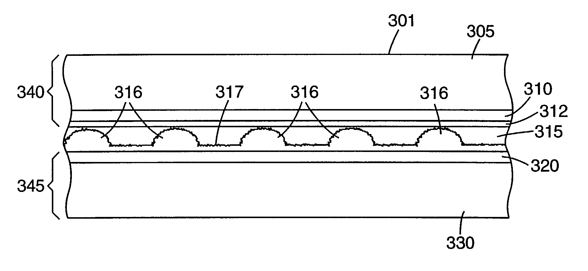
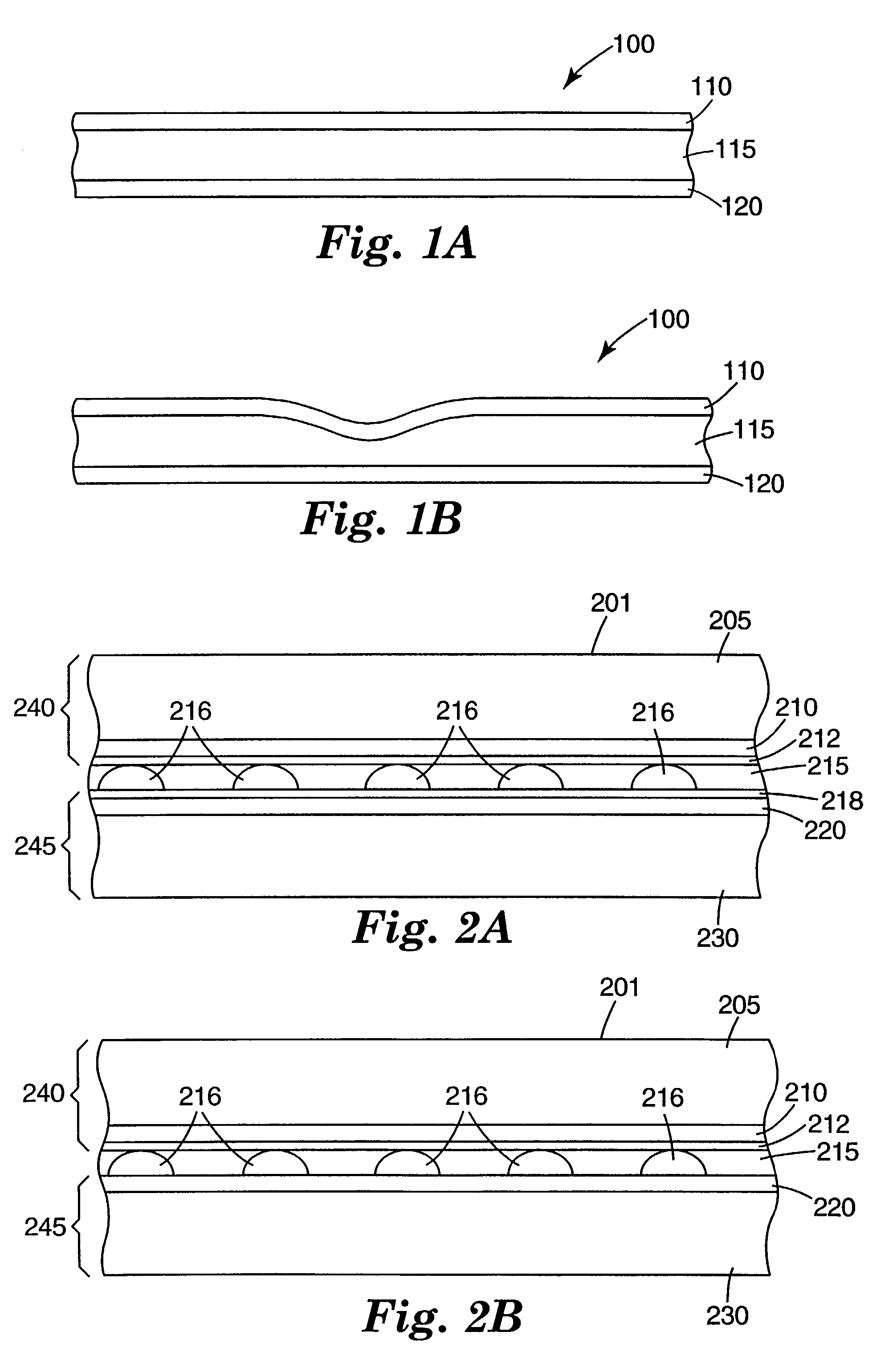
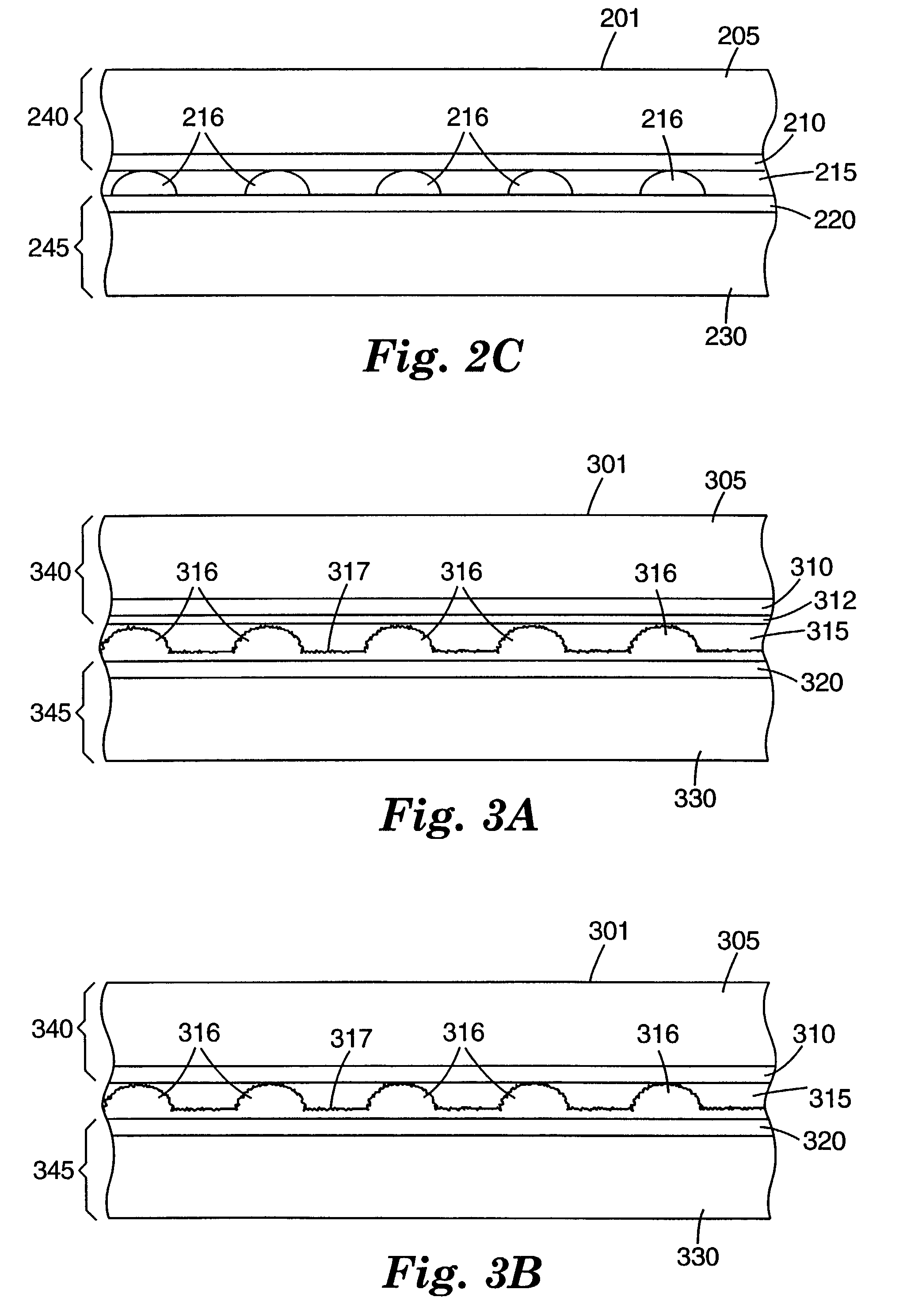
[0031]In the following description of the illustrated embodiments, references are made to the accompanying drawings which form a part hereof, and in which is shown by way of illustration, various embodiments by which the invention may be practiced. It is to be understood that other embodiments may be utilized, and structural and functional changes may be made without departing from the scope of the present invention.

[0032]As stated above, and for other reasons stated below which will become apparent upon reading the present specification, there is a need for a durable touch sensor that reliably and accurately detects the location of a touch independent of the touching implement used. There exists a further need for such a touch sensor with improved optical characteristics and durability. There exists a further need for a touch sensor that can be used with simplified control circuitry.

[0033]The present invention provides, among other things, a touch sensor designed to increase optica...


PUM


Abstract

A touch sensing method and a touch sensing device are described for sensing a location of a touch. When the touch sensing device is touched, a first conductive layer disposed on a supporting layer is deflected toward a second conductive layer. The touch location is determined by sensing the change in capacitance at the location of the touch. A change in capacitance at the touch location is sensed by driving one of the conductive layers with an electrical signal referenced to the other conductive layer and measuring the current flow between the conductive layers. The sensed change in capacitance is greater than a change in the external capacitance of the touch sensor.

Description

FIELD OF THE INVENTION[0001]The present invention is directed generally to a touch sensor, and more particularly to a durable, transparent touch sensor.BACKGROUND[0002]Touch sensors are increasingly popular devices because they provide a natural interface between an electronic system and operator. Rather than using a keyboard to type in data, for example, touch sensors allow the user to transfer information to a computer by touching a displayed icon, or by writing or drawing on a screen. It is desirable in many applications for the touch screen to be transparent and positioned over a display.[0003]Several types of transparent touch sensors use resistive or capacitive techniques to detect touch location. A resistive touch sensor includes two layers of transparent conductive material, such as a transparent conductive oxide, separated by a gap. When touched with sufficient force, one of the conductive layers flexes to make contact with the other conductive layer. The location of the co...

Claims


Application Information

Patent Timeline
Patent Type & Authority Patents(United States)
IPC IPC(8): G09G5/00G01B7/00G06F3/033G06F3/041G06F3/044G06F3/048
CPCG06F3/0412G06F3/0488G06F3/044G06F3/0414G06F3/0445G06F3/0447
Inventor CROSS, ELISA M.MOSHREFZADEH, ROBERT S.CHERNEFSKY, ANTHONY F.BOTTARI, FRANK J.CORDEIRO, CRAIG A.SCHULZ, STEPHEN C.KARDAUSKAS, MICHAEL J.
Owner 3M INNOVATIVE PROPERTIES CO
Why Eureka
Try Eureka