Audio circuitry for dynamics reduction

a technology of audio circuitry and dynamics, applied in the field of low-frequency circuits, can solve the problems of loss of valuable signal-to-noise ratio, loss of signal quality, distortion at locations in the circuit, etc., and achieve the effect of simple, economical design and high degree of adjustability

Inactive Publication Date: 2006-12-26
RED CHIP
View PDF4 Cites 2 Cited by
  • Summary
  • Abstract
  • Description
  • Claims
  • Application Information

AI Technical Summary

Benefits of technology

[0006]Given this prior art, one of the objects of the various embodiments described herein is to create a low-frequency circuit of the type referred to above that provides a high degree of adjustability combined with a simple, economical design.

Problems solved by technology

These measures are either associated with a loss of valuable signal-to-noise ratio or other losses in signal quality.
One problem with this approach is that distortion occurs at locations in the circuit that usually have an extremely undesirable effect on the desired result.
However, such amplifiers usually have a relatively high level of technical complexity, and they suffer from disadvantages relating to the principle itself—such as audible control processes, slow response, and control intermodulation.

Method used


Image

  • Audio circuitry for dynamics reduction
  • Audio circuitry for dynamics reduction
  • Audio circuitry for dynamics reduction

Examples


Embodiment Construction

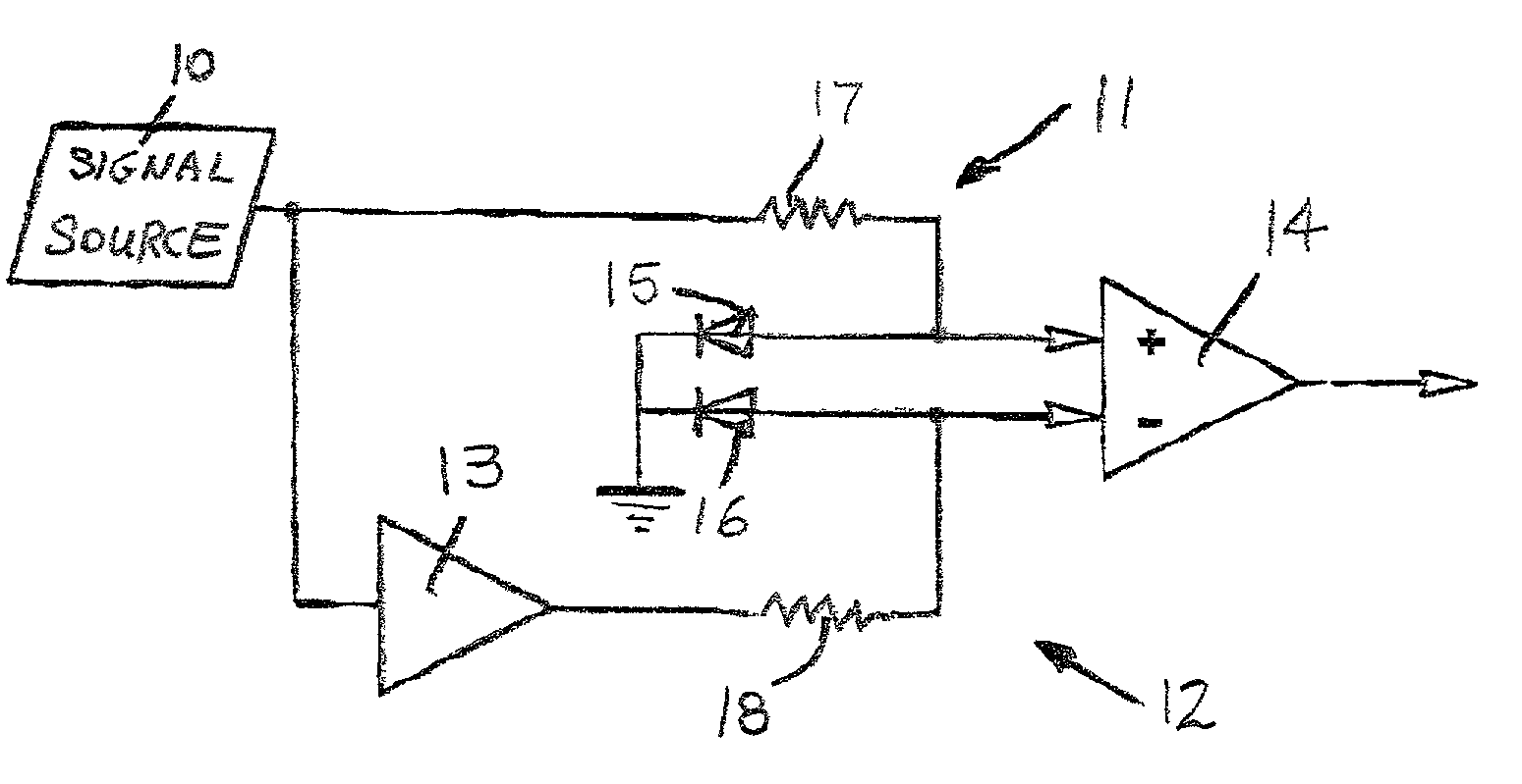
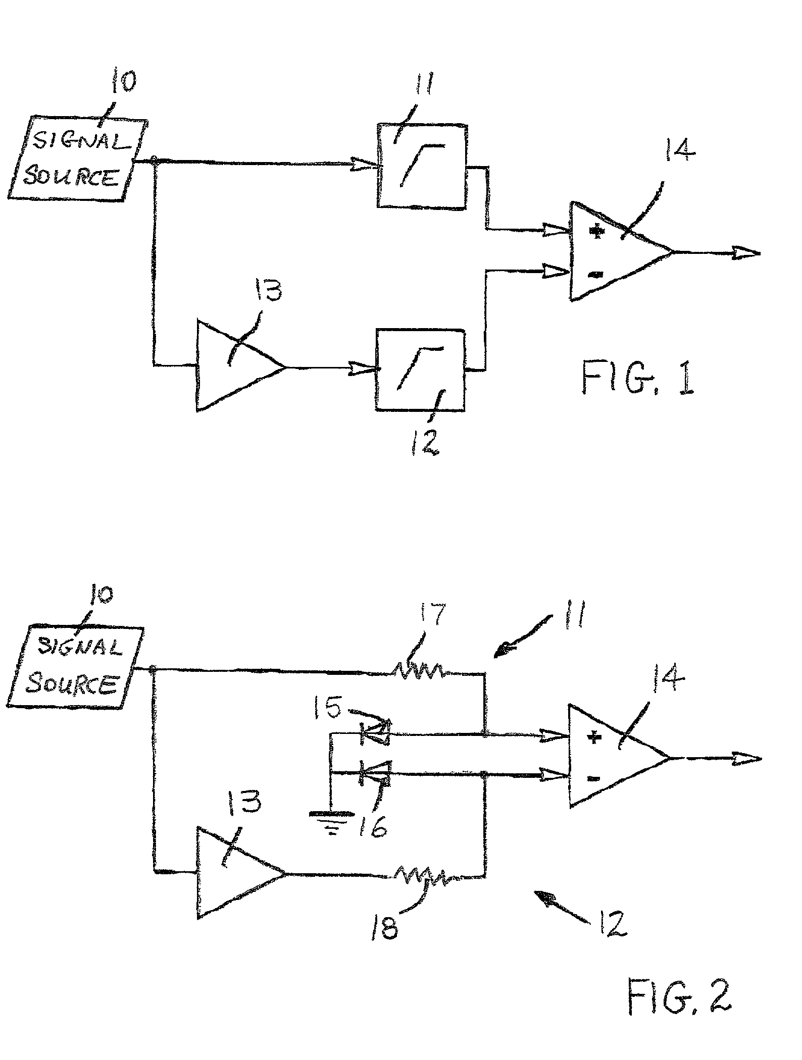
[0022]FIG. 1 is a schematic diagram that shows the general design of a low-frequency circuit used to process audio signals. An audio signal is supplied by a signal source 10. In the embodiment shown here, this audio signal from signal source 10 has an asymmetrical shape. This means that relative to ground, the(signal source 10 produces an audio signal having a specified phase orientation. This audio signal is supplied to the low-frequency circuit. This circuit comprises a first input stage 11 and a second input stage 12. The two input stages, 11 and 12, preferably are designed in an essentially identical way and essentially have the same nonlinear performance curves. These input stages can be designed as passive elements as will be described below based on FIG. 2. Alternatively, input stages 11 and 12 can be active elements based on amplifiers, etc.

[0023]The audio signal supplied by the signal source 10 is fed into the input of input stage 11. An inverter 13 is located ahead of the ...


PUM


Abstract

A circuit for processing an audio signal includes an input stage to which the audio signal is applied and an output at which the processed audio signal is presented. The circuit comprises first and second input stages (11, 12) having nonlinear performance curves, the first stage receiving the audio signal at a specified phase, and the second stage receiving from an inverter (13) an inverse phase of the audio signal. A positive half wave of the input signal is processed nonlinearly and the negative half wave is processed linearly. A difference amplifier (14) receives the signals produced by the first and second input stages and generates an audio signal representing a difference between the signals present at its inputs.

Description

RELATED APPLICATION[0001]This application claims priority under 35 U.S.C. § 119 of German Patent Application No. 100 15 833.1-42, filed Mar. 30, 2000, for NIEDERFREQUENZSCHALTUNG ZUR DYNAMIKBEGRUNZUNG.TECHNICAL FIELD[0002]This invention relates to a low-frequency circuit for processing audio signals, and in particular to an input stage and / or an impedance transformer for audio devices having an input at which an audio signal is present and an output at which the processed audio signal is present.BACKGROUND OF THE INVENTION[0003]In conventional audio input stages, in particular in the input stages of musical instrument amplifiers, modules are used for impedance transformation and preamplification. If possible, these modules are operated in their linear operating ranges in order to avoid undesirable distortion products in the output signal. Once this linear working range is left, more-or-less clearly audible and measurable nonlinear distortions occur. To avoid these distortions, measu...

Claims


Application Information

Patent Timeline
Patent Type & Authority Patents(United States)
IPC IPC(8): H03F21/00H03F3/217H03F3/38H03F99/00H03G7/06H03G11/00
CPCH03G7/06H03G11/002
Inventor BEHRINGER, ULIDUWE, JAN
Owner RED CHIP
Why Eureka
Try Eureka