
Device for mounting decorative and functional items

a technology for decorative items and devices, applied in the direction of writing aids, manufacturing tools, instruments, etc., can solve the problems of many other ways, kelly devices do not provide a single step, and hideall disclosure does not provide a method for hanging heavier pictures

Inactive Publication Date: 2007-01-02
CARBONARO GREGORY S
View PDF13 Cites 50 Cited by
  • Summary
  • Abstract
  • Description
  • Claims
  • Application Information

AI Technical Summary

Benefits of technology

[0009]In view of the disadvantages inherent in known types of picture hanging devices, some of which have been identified above, the present invention provides a new, time-efficient and first-time accurate hanging device for pictures, sconces, decorative shelves, clocks, artwork, mirrors and other decorative and functional items that can be used for easy centering, leveling, marking, and hanging thereof in a targeted location even when integral mounting holes and clips placed thereon during manufacture are misaligned.
[0015]An object of the present invention is to provide a picture, sconce, decorative shelf, clock, artwork, mirror and other decorative or functional item hanging device for allowing the easy centering, leveling, first-time accurate marking, and hanging of a wide variety of such items.
[0017]Another object is to provide a picture, sconce, decorative shelf, clock, artwork, mirror, and other decorative or functional item hanging device that will hold the item to be hung or mounted at a pre-determined stand off distance safely away from the wall, or other surface intended for hanging or mounting the item, while the item is being moved and positioned for its final placement so that neither the present invention nor the item will injure the targeted mounting wall or surface, with the stand offs being compressible or flexible so that once the final hanging position in a targeted location is selected, a wall-ward force applied to the hanging device will compress the flexible or compressible stand off and bring the integral marking implements into contact with the wall at the locations needed for wall hook placement.
[0019]Another object is to provide a picture, sconce, decorative shelf, clock, artwork, mirror, and decorative or functional item hanging device that will have adjustable position temporary hooks with integral pencil or marking implement holders in perfect alignment with and mounted directly behind each temporary hook, so that the tip of a pencil or other marking implement used will come into contact with the wall when final position of the item to be hung is visually centered and leveled by the installer and the installer then compresses the flexible or compressible stand off distance using a wall-ward push to bring the tip of the marking implement or implements into contact with the surface of the wall or other mounting surface to mark the exact position needed for wall hook placement and achieve first-time accurate, centered and level item mounting.

Problems solved by technology

However, the Hindall disclosure does not provide a method for hanging heavier pictures requiring more than one hook.
However the Kelly device does not provide a single step for positioning a picture on the wall and marking the position where a user wants it hung.
The Rimback device addresses and overcomes some of the problems with prior art picture hangers, but is deficient in many other ways, including the hanging of other types of decorative and functional wall items.
The main problems with conventional picture hanging devices are that they are primarily for hanging pictures and are deficient in the area of hanging other two-hook items such as wall sconces, decorative shelves, mirrors, clocks, and pictures with integral mounting holes or mounting clips of differing widths.
While the Rimback device will allow for the hanging of items needing one or two wall hooks, an important limitation of the Rimback device is that its alignment hooks and marking holes are in fixed, pre-determined and non-adjustable positions.
Consequently the Rimback device does not lend itself well to the vast variance of widths found between mounting holes and mounting clips on items intended for wall mounting, such as but not limited to wall sconces, decorative shelves, mirrors and some pictures.
Because of this, the Rimback device and others like it are limited primarily to hanging wire mounted pictures, wherein the spacing or width between the placement of the wall hooks is not critical to hanging.
However, items intended for vertical hanging which have two or more integral fixed position mounting holes or mounting clips are nearly impossible to hang with the Rimback device and other similar prior art devices, to include decorative items designed to be wall-mounted that are “one-of-a-kind” works of decorative art when it comes to mounting them.
For although several of theses “one-of-a-kind” works may appear to be duplicates of one another, or near duplicates, from the front, each is produced without the precision of automation and consequently has integral mounting holes or mounting clips that vary widely in spacing and frequently are out of alignment with each other.
As a result, fixed width, non-adjustable hanging devices, such as the Rimback and similar prior art hanging devices, can not be used effectively to hang such “one-of-a-kind” items, as their non-adjustable fixed width mounting capability can not accommodate the vast variations in mounting hole or mounting clip widths existing in a wide array of decorative and functional wall items.
Another problem with conventional picture hanging devices is that the integral mounting holes or mounting clips on many hand made wall sconces, decorative shelves, mirrors, pictures, and other items are markedly out of alignment relative to each other and, in a similar manner to the “one-of-a-kind” items mentioned above, and use of level markings on a wall for placement of wall hooks to hang them will not result in a wall-mounted item with a level appearance.
This variation in alignment makes it highly improbable that an installer using any of the currently available hanging devices will be able to mark a wall for hook placement so that unique decorative items can be hung level without having to make at east one surplus hole in the wall.
Another problem with conventional picture hanging devices is that they often damage, mark or scrape the wall around a targeted hanging location as they are being used to position a picture.
This is because they provide no mechanism or means to hold the picture away from the wall prior to and after wall marking, or prevent the edges of the picture or the apparatus itself from contacting the wall while it is being used.
While known prior art devices may be suitable for the particular purpose they address, they are not generally as versatile as the present invention, which allows easy positioning and time-saving leveling, marking and hanging of all types of pictures, sconces, decorative shelves, artwork, clocks, mirrors and other devices from a vertically extending surface.
The main problem with known picture hanging devices is that they are primarily effective for hanging pictures on a wall from a single hook and typically deficient in the area of hanging items requiring two wall hooks, particularly wall sconces, decorative shelves, mirrors, artwork, and pictures with integral mounting holes or mounting clips having differing spaced-apart widths.
Although the Rimback and other similar devices will allow for the hanging of items with one or two hooks, they are significantly limited by their alignment hooks and marking holes being in fixed, non-adjustable positions.
Because of this, the Rimback and other similar hanging devices are limited primarily to hanging wire mounted pictures, since with wire mounted pictures the spacing or width between the placement of the wall hooks is not critical to hanging.

Method used


Image

  • Device for mounting decorative and functional items
  • Device for mounting decorative and functional items
  • Device for mounting decorative and functional items

Examples


Embodiment Construction

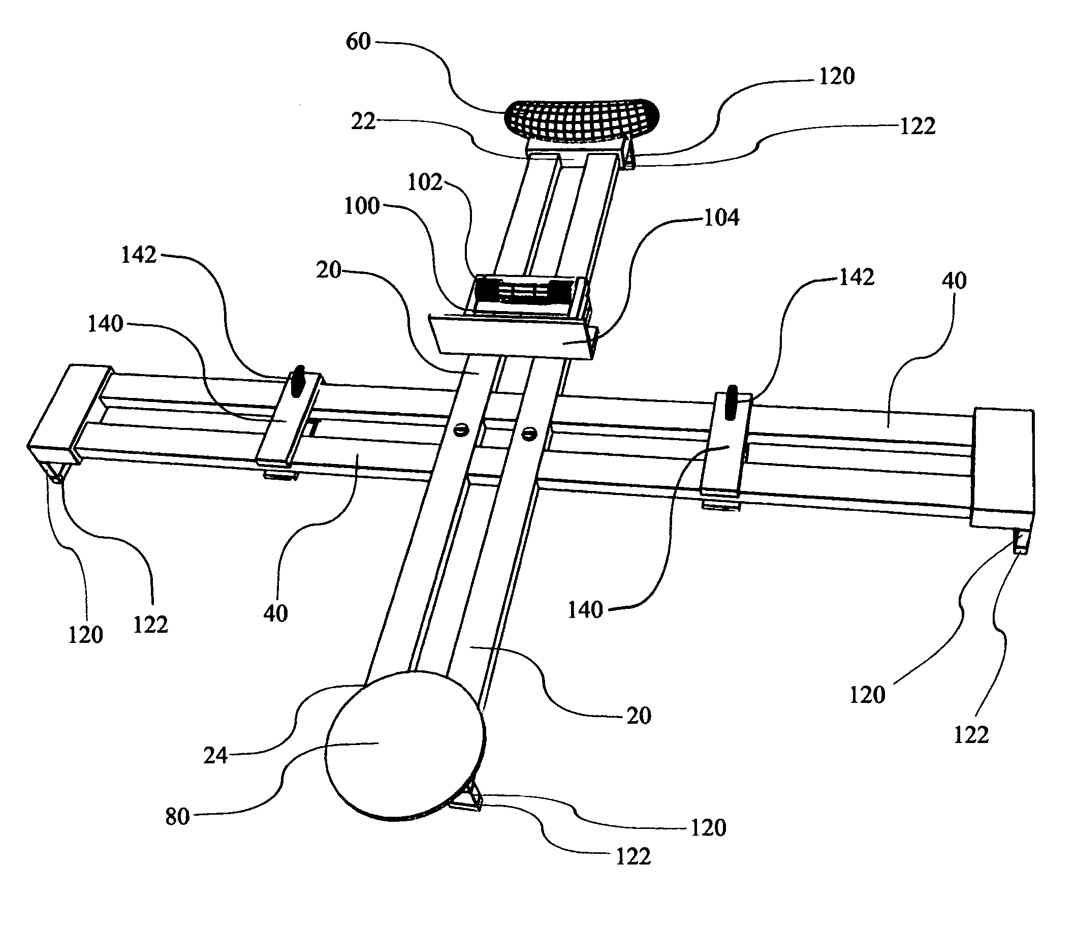
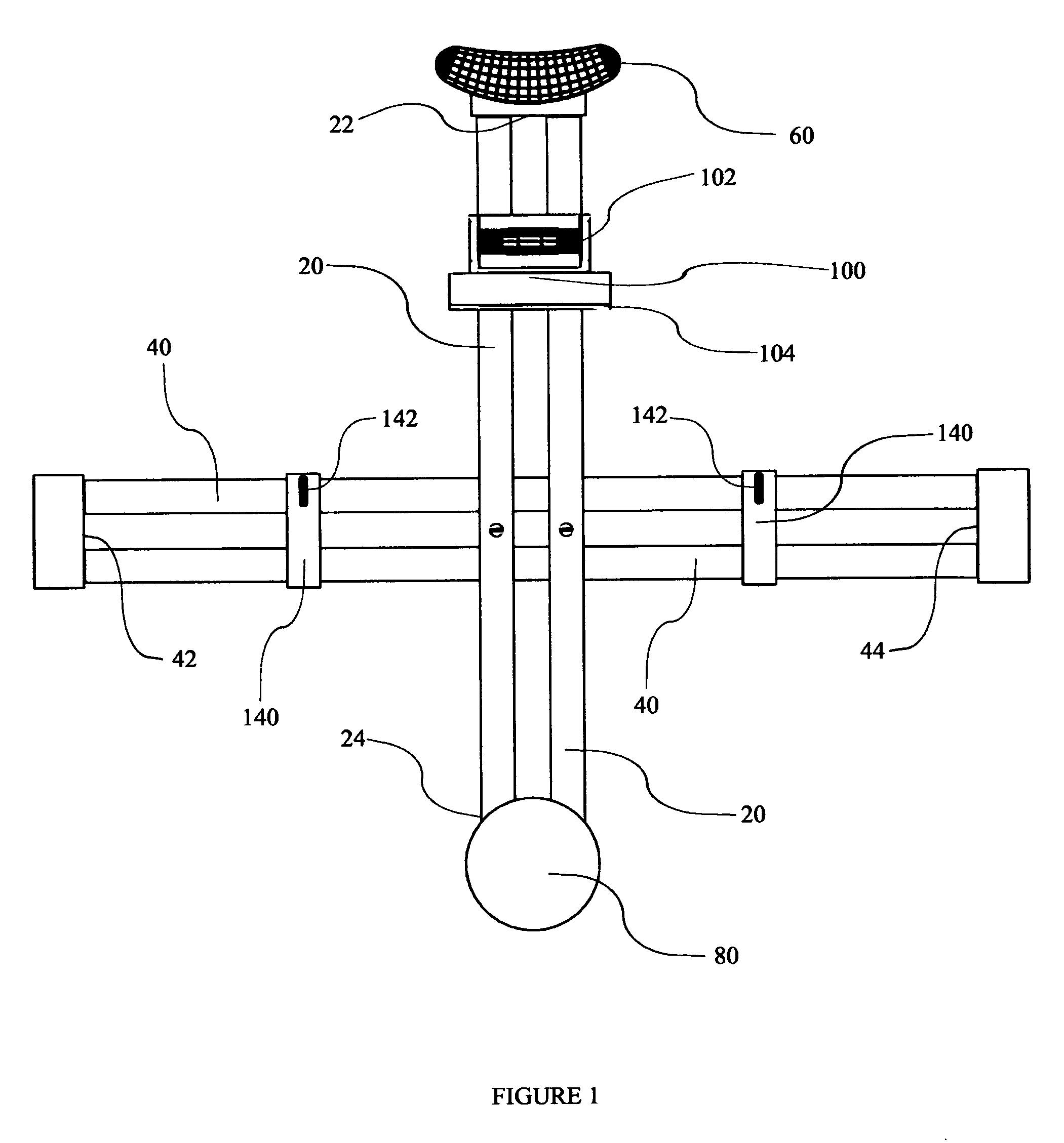
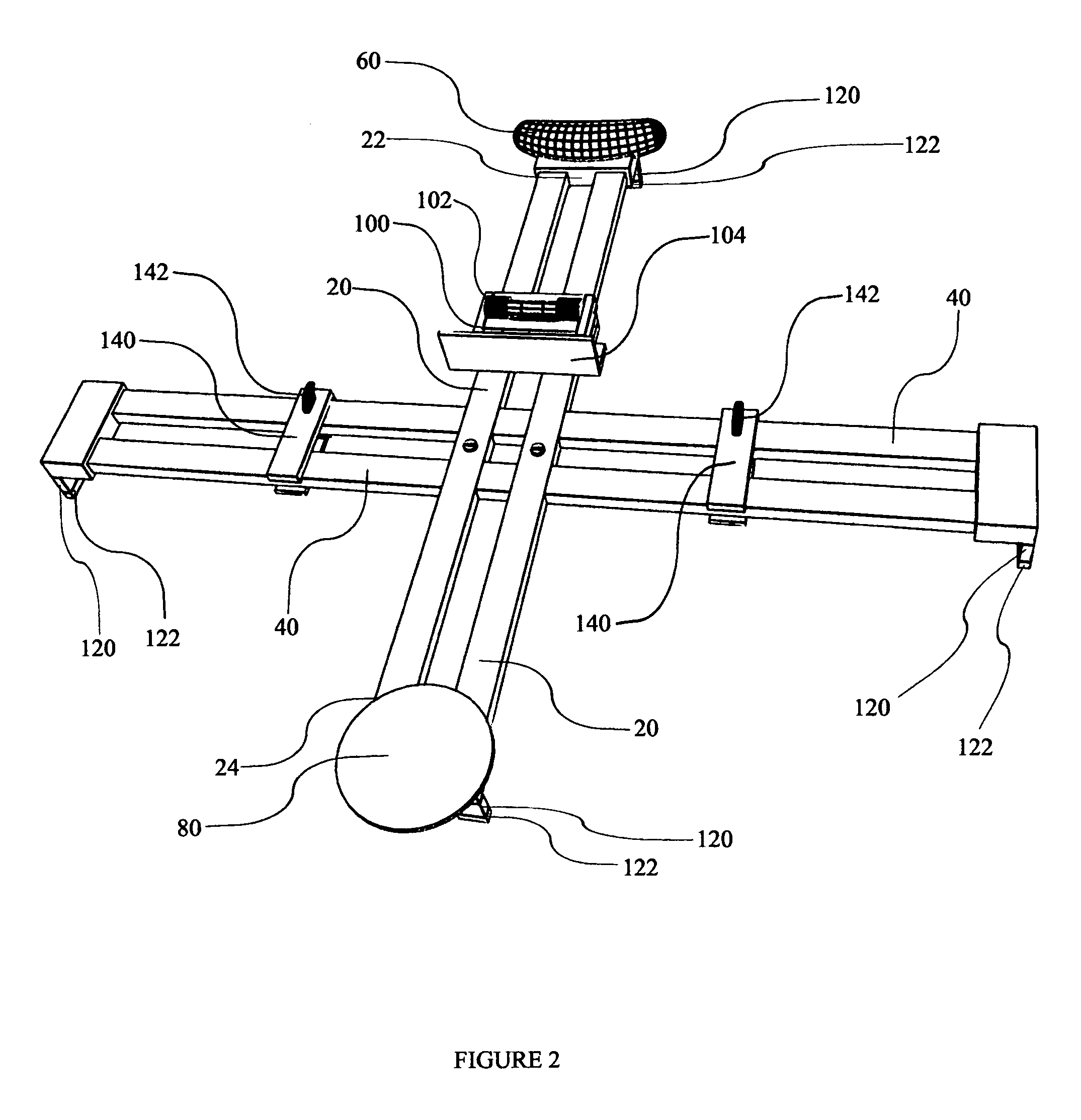
[0035]Turning now descriptively to the drawings, in which similar reference characters denote similar elements throughout the several views, FIGS. 1–12, the attached FIGS. 1–12 illustrate a picture, sconce, decorative shelf, clock, artwork, mirror, and other decorative or functional item hanging device, or selected components thereof, which comprises an elongated Vertical Support member 20 attached centrally to an elongated Horizontal Support member 40. Although FIG. 1 shows such attachment via two threaded fasteners and easily removable fastening means is preferred for compact packaging, transport and storage, the type of attachment means used is not critical and permanent attachment means between Vertical Support member 20 and Horizontal Support member 40 is also contemplated. Releasable attachment means also allows for substitution of longer and shorter Support members and Horizontal Support members for quick and easy adaptation of the present invention for enhanced installation ...


PUM


Abstract

A device for easy positioning, leveling, marking and hanging of all types of pictures, sconces, decorative shelves, mirrors, and other devices to be mounted on a support surface. It has elongated vertical and horizontal support members attached together, each preferably with resilient legs. The vertical support has a handle at one end, a surface rest at its other end, and a rotatable sliding level. Sliding hook clips are positioned along the horizontal support, each having a front hook for holding an item to be hung while positioning and marking with an opposed marking implement take place. One or more hook clips can be used simultaneously. Flexing or compression of legs, soft pads, vertical support member, and / or horizontal support member reduces the wall stand-off distance of the device and causes the aligned marking implements to contact and mark the wall exactly where the held item should be permanently mounted.

Description

CROSS-REFERENCES TO RELATED APPLICATIONS[0001]This patent application relates to the currently pending U.S. provisional patent application Ser. No. 60 / 553,436, which was filed on Mar. 16, 2004 by the same inventor and for substantially the same subject matter. All benefit of such co-pending provisional patent application is herein requested.BACKGROUND OF THE INVENTION[0002]1. Field of the Invention[0003]The present invention relates generally to devices for hanging objects from a wall, such as picture hanging devices, and more specifically it relates to a picture, sconce, decorative shelf and mirror hanging device for allowing easy positioning, leveling, marking and hanging of all types of pictures, sconces, decorative shelves, mirrors, clocks, artwork, and / or other objects that one might want to hang in a level orientation from a specifically targeted area on a vertically extending surface, such as but not limited to a wall.[0004]2. Description of the Related Art[0005]It can be app...

Claims


Application Information

Patent Timeline
Patent Type & Authority Patents(United States)
IPC IPC(8): B25H7/04G01B5/24
CPCA47G1/205
Inventor CARBONARO, GREGORY S.
Owner CARBONARO GREGORY S
Learn More