Projector for compensating chromatic aberration of magnification

a projector and magnification compensation technology, applied in the field of projectors, can solve the problems of deteriorating the cooling feature of the electrooptical device, difficult to fabricate a lens element or a prism element, and reducing the size of the projected image screen of the three kinds of color light. , to achieve the effect of minimizing the cooling feature and facilitating the integration of optical elements

Inactive Publication Date: 2007-01-02
SEIKO EPSON CORP
View PDF27 Cites 6 Cited by
  • Summary
  • Abstract
  • Description
  • Claims
  • Application Information

AI Technical Summary

Benefits of technology

[0008]With this structure, since the polarizing plate and the corresponding optical element for compensating chromatic aberration of magnification are integrated into one substrate, the space for these components can be effectively utilized, thereby minimizing deterioration of the cooling feature of the electrooptical device. Also, the structure has an advantage in that it is easier to integrate the optical element for compensating chromatic aberration of magnification, such as a lens element or a prism element, with the corresponding polarizing plate than to integrate the optical elements for compensating chromatic aberration of magnification with a color-light-synthesizing prism.
[0009]Also, in the above case, the projector may have a structure in which the parent material of the polarizing plate disposed on the light path of the red light is composed of glass or a light-transmissive resin, the parent material of the polarizing plates disposed on the light paths of the green and blue light are composed of sapphire or quart crystal, and the optical element for compensating chromatic aberration of magnification is disposed only on the light path of the red light. Since the polarizing plate disposed on the light path of the red light has a wider temperature allowance than those disposed on the light paths of the other kinds of color light, in place of thermally conductive quartz crystal or sapphire, glass or resin having better workability than the quartz crystal or sapphire can be used as the parent material of the polarizing plate used for the red light. Accordingly, a lens element or a prism element can be easily formed on an integrally with the polarizing plate used for the red light by making use of its parent material.
[0011]With this structure, since the angle-of-field compensating film and the corresponding optical element for compensating chromatic aberration of magnification are integrated into one substrate, the space for these components can be effectively utilized, thereby minimizing deterioration of the cooling feature of electrooptical device. Also, it is easier to integrate the optical element for compensating chromatic aberration of magnification, such as a lens element or a prism element, with the corresponding angle-of-field compensating film than to integrate the optical elements with a color-light-synthesizing prism.
[0012]In addition, each of the above-described projectors is characterized in that, when the optical axis of the projection optical system is shifted (moved) in parallel to at least one of two directions mutually perpendicular to the system optical axis, the optical axis of the optical element for compensating chromatic aberration of magnification is shifted in parallel to a predetermined direction, following the shift of the optical axis of the projection optical system. With this structure, even when the projection optical system is shifted, compensation of chromatic aberration of magnification of a projected image screen can be properly performed. The system optical axis stated here is a hypothetical axis formed by a series of optical elements disposed on the light path upstream of the projection optical system and substantially coincides with the center axis of light fluxes incident on the projection optical system.
[0013]Meanwhile, in the above-mentioned case, the optical element preferably has no refraction feature on a plane extending orthogonal to the predetermined direction and including the generating line thereof and has a refraction feature on a plane extending orthogonal to the generating line thereof. With this structure, of differences in sizes of the projected image screens of the corresponding kinds of color light, caused by the chromatic aberration of magnification of the projection optical system, differences in sizes of the projected image screens extending along a direction perpendicular to the generating line can be reduced.

Problems solved by technology

Unfortunately, the projection optical system generally has chromatic aberration of magnification, thereby often causing a problem in that the sizes of projected image screens of the three kinds of color light are different from one another.
Unfortunately, since the space from the emitting surface of each electrooptical device to the incident surface of the color-light-synthesizing prism is narrow, disposition of an additional lens element or prism element in the space makes the space narrower, thereby deteriorating the cooling feature of the electrooptical device.
Also, it is often difficult to fabricate a lens element or a prism element in order to dispose it on the incident surface of the color-light-synthesizing prism, when the shape and the function of the color-light-synthesizing prism are taken into consideration.

Method used


Image

  • Projector for compensating chromatic aberration of magnification
  • Projector for compensating chromatic aberration of magnification
  • Projector for compensating chromatic aberration of magnification

Examples


Embodiment Construction

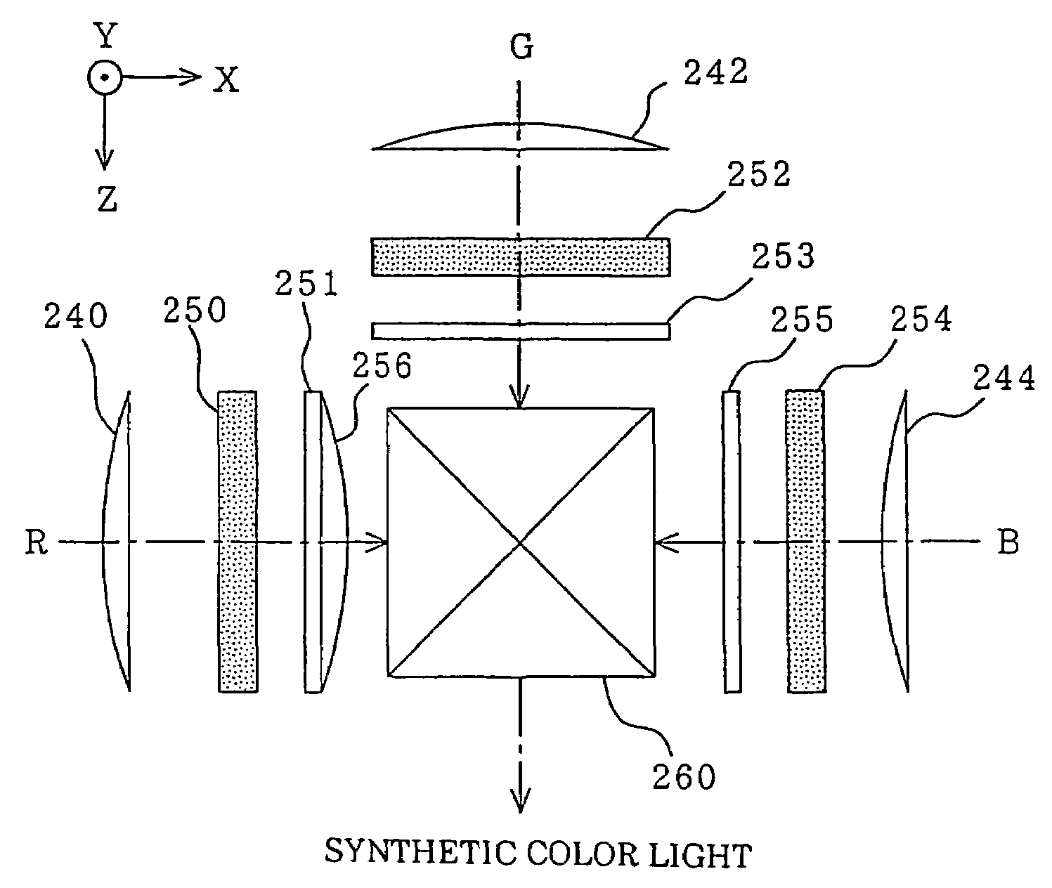
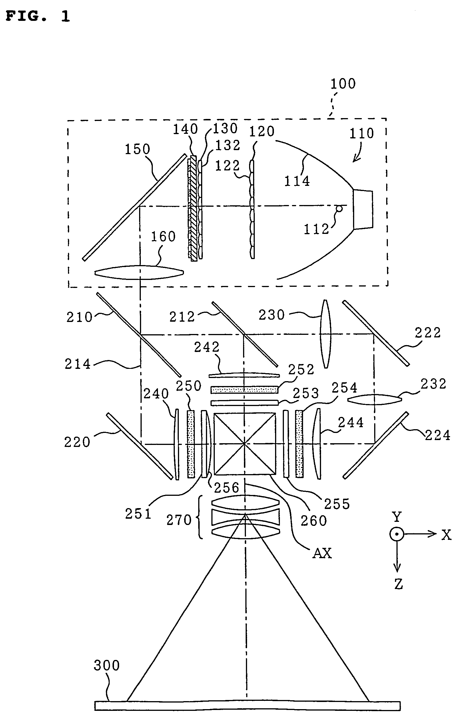
[0026]FIG. 1 is a plan view of the schematic structure of an overall optical system of a projector according to an embodiment of the present invention. The projector includes an illumination optical system 100; dichroic mirrors 210 and 212; reflecting mirrors 220, 222 and 224; an incident-side lens 230; a relay lens 232; three field lenses 240, 242 and 244; three liquid crystal panels 250, 252 and 254 serving as electrooptical devices; polarizing plates 251, 253 and 255 corresponding to the foregoing liquid crystal panels; a cross-dichroic prism (color-light-synthesizing prism) 260 serving as a color-light-synthesizing optical system; and a projection lens 270 serving as a projection optical system.

[0027]The illumination optical system 100 includes a light source 110 emitting light fluxes in a predetermined direction; a first lens array 120; a second lens array 130; a polarization-conversing element 140; a reflecting mirror 150; and a superimposing lens 160. The first and second len...


PUM

PropertyMeasurementUnit
coloraaaaaaaaaa
sizeaaaaaaaaaa
chromatic aberrationaaaaaaaaaa

Abstract

A projector having a cross-dichroic prism (260) synthesizing three kinds of red, green, and blue light emitted from liquid crystal panels (250, 252, 254); and a projection lens (270) projecting the synthesized light and also having polarizing plates (251, 253, 255) disposed on the optical paths between the corresponding liquid crystal panels (250, 252, 254) and the cross-dichroic prism (260) includes a lens element (256), serving as an optical element for compensating chromatic aberration of magnification, which is formed on and integrally with one surface of the polarizing plate (251) disposed on the light path of the red light and which adjusts the size of the projected image screen of the red light extending along at least a predetermined direction so as to be nearly equal to those of the projected image screens of the other kinds of color light extending along the predetermined direction.

Description

TECHNICAL FIELD [0001]The present invention relates to a projector, and more particularly, it relates to compensation of chromatic aberration of magnification-of a projected image screen.BACKGROUND ART [0002]A projector projecting and displaying a color image includes an illumination optical system, a color-light-separating optical system, liquid-crystal panels for corresponding kinds of separated color light, a color-light-synthesizing optical system, and a projection optical system. Light emitted from the illumination optical system is separated into three kinds of red, green, and blue light by the color-light-separating optical system, and the three kinds of color light are modulated by corresponding liquid crystal panels so as to generate corresponding images. Then, these images are synthesized by the color-light-synthesizing optical system and are projected by the projection optical system. The projection optical system focuses the three kinds of synthesized color light on a pr...

Claims


Application Information

Patent Timeline
Patent Type & Authority Patents(United States)
IPC IPC(8): G03B21/14G03B21/00G03B21/20G02B27/00G02B27/14G02B27/28H04N9/31
CPCG02B27/0025G02B27/1046G02B27/149H04N9/3197G03B21/00H04N9/3105G02B27/288G03B21/005G02B27/28
Inventor KAWAI, FUMIENISHIDA, KAZUHIRONARIMATSU, SHUJI
Owner SEIKO EPSON CORP
Why Eureka
Try Eureka