
Apparatus for simultaneous cleaning of a liquid and a gas

a simultaneous cleaning and apparatus technology, applied in the direction of centrifuges, lubricant mounting/connection, separation processes, etc., can solve the problems of relatively poor gas cleaning efficiency high cost of conical separation discs, and relatively high production cost of apparatus designed in this way. achieve the effect of effective cleaning of gas, efficient gas cleaning, and relatively inexpensive production

Inactive Publication Date: 2007-01-02
ALFA LAVAL CORP AB
View PDF19 Cites 32 Cited by
  • Summary
  • Abstract
  • Description
  • Claims
  • Application Information

AI Technical Summary

Benefits of technology

This configuration achieves a high gas cleaning efficiency while keeping the apparatus relatively inexpensive to manufacture, with the separation discs effectively removing particles from the gas and maintaining the rotor's cleanliness by allowing easy particle disposal, and the design requires less energy for rotor rotation due to optimal placement.

Problems solved by technology

An apparatus designed in this way is relatively expensive to manufacture.
Particularly the conical separation discs are expensive.
An apparatus designed in this way has a relatively poor gas cleaning efficiency.
Even an apparatus designed in this way has a relatively poor gas cleaning efficiency.

Method used


Image

  • Apparatus for simultaneous cleaning of a liquid and a gas
  • Apparatus for simultaneous cleaning of a liquid and a gas
  • Apparatus for simultaneous cleaning of a liquid and a gas

Examples


Embodiment Construction

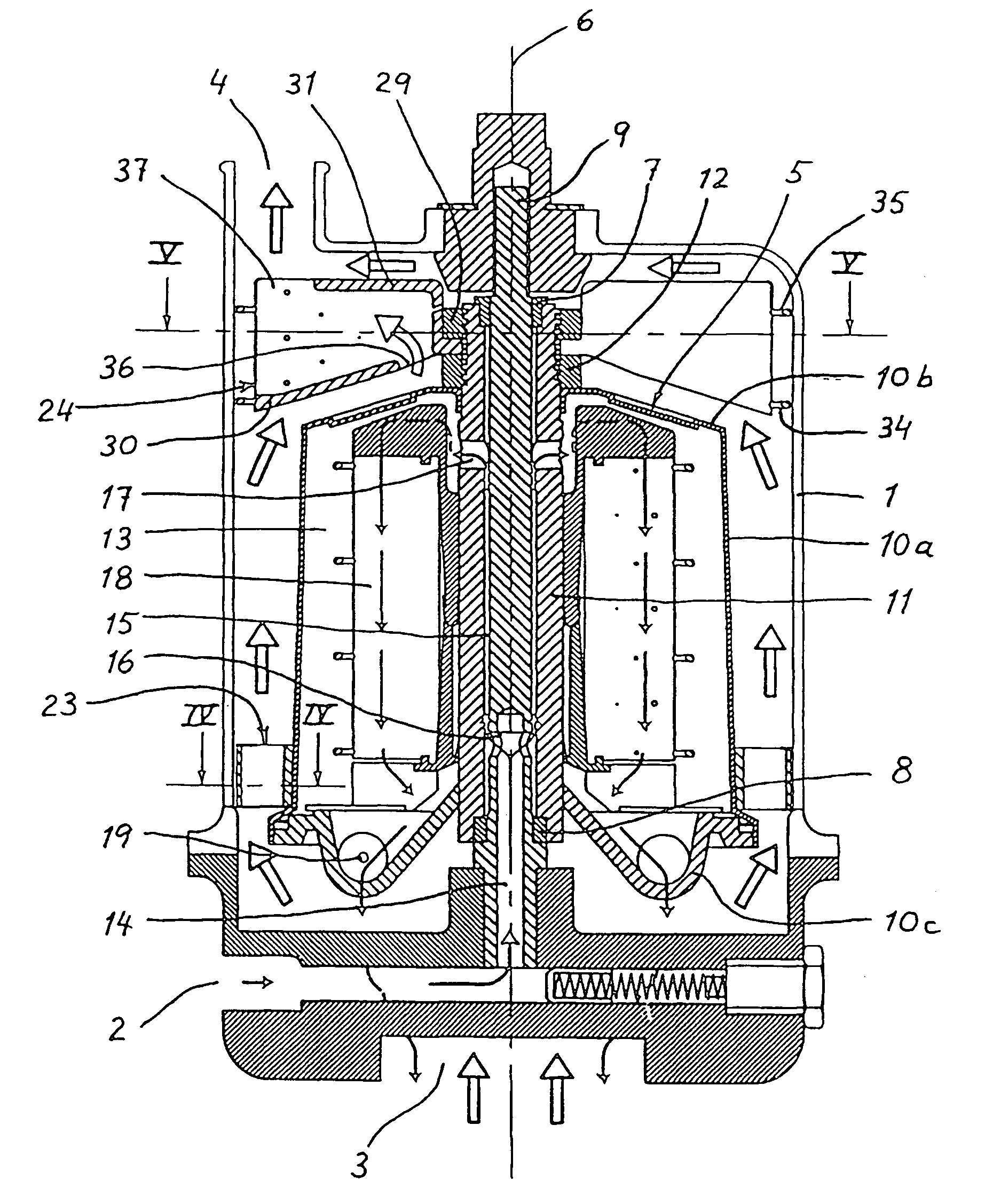
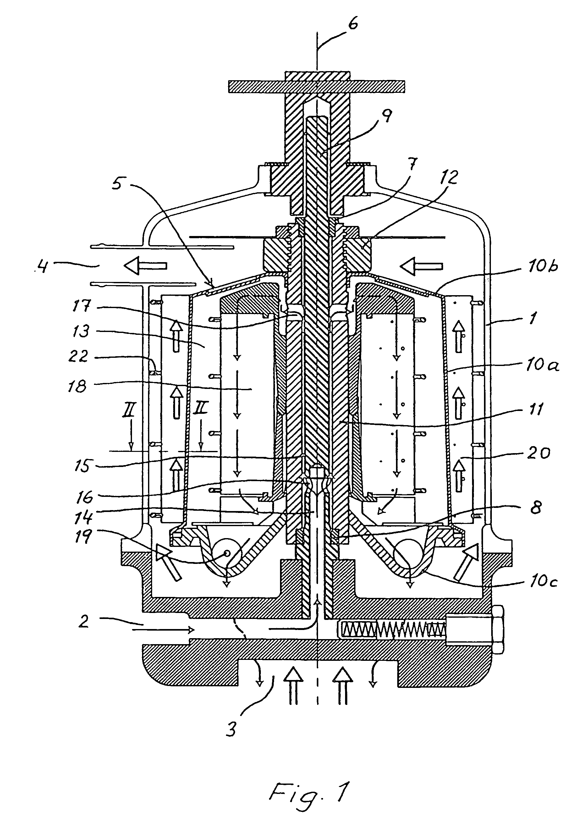
[0020]The FIGS. 1 and 2 show a first embodiment of an apparatus for simultaneous cleaning of a liquid and a gas. The apparatus includes a stationary housing 1, which has an inlet 2 for liquid to be cleaned and an inlet 3 for gas to be cleaned. The liquid can be constituted by lubricating oil circulating through an internal combustion engine during its operation, and the gas can be constituted by crankcase gas coming from the same combustion engine. The lubricating oil includes among other things soot particles to be separated, and the crankcase gas includes a mixture of soot particles and oil particles to be separated. The housing 1 has a separate outlet 4 for cleaned gas, whereas said inlet 3 for gas to be cleaned also serves as an outlet for cleaned liquid.

[0021]Within the housing 1 a centrifugal rotor 5 is arranged to rotate around a vertical centre axis 6. The rotor 5 is supported in two bearings 7 and 8 by a central stationary column 9, that is fixed at its lower part and at it...


PUM


Abstract

An apparatus for simultaneous cleaning of a liquid and a gas includes a centrifugal rotor delimiting in a casing a separation chamber that is arranged for through flow and cleaning of the liquid. On the outside of the casing separation discs are mounted for rotation with the centrifugal rotor. Between the separation discs there are formed axially extending separation passages formed for through flow and cleaning of the gas.

Description

CROSS-REFERENCE TO RELATED APPLICATIONS[0001]This application is a divisional application of U.S. patent application Ser. No. 10 / 492,736 filed on Jul. 14, 2004, now U.S. Pat. No. 7,081,146 which is hereby incorporated by reference, and is entitled to the benefit of and incorporates by reference subject matter disclosed in International Application No. PCT / SE02 / 01971 filed on Oct. 30, 2002 and Swedish Patent Application No. 0103631-8 filed on Nov. 1, 2001.FIELD OF THE INVENTION[0002]The present invention relates to an apparatus for simultaneous cleaning of a liquid from first particles suspended therein and cleaning of a gas from second particles suspended therein. The apparatus includes a centrifugal rotor that is rotatable about a rotational axis and that delimits a separation chamber arranged for through flow and cleaning of said liquid, a driving device for rotation of the centrifugal rotor about said rotational axis and a gas cleaning device that is connected with the centrifuga...

Claims


Application Information

Patent Timeline
Patent Type & Authority Patents(United States)
IPC IPC(8): B04B5/12B01D45/12F01M13/04B04B1/06B04B1/04B04B5/00B04B7/08B04B7/12F01M11/03
CPCB01D45/12B04B1/04B04B5/005B04B5/12B04B7/12B04B7/08Y10S55/19B04B2005/125F01M2001/1035B04B5/06
Inventor HALLGREN, INGVARLARSSON, LEIFLJUNGTSTROM, ROLF
Owner ALFA LAVAL CORP AB
Learn More