Unlock instant, AI-driven research and patent intelligence for your innovation.

Non-contact rotation angle detecting sensor

a technology of rotation angle and detection sensor, which is applied in the direction of measuring devices, instruments, using electrical means, etc., can solve the problems of inability to achieve desired accuracy, inability to apply these measures to a case of mass production such as a vehicle in consideration of variations in the manufacture or technical variations in products, and high cost of anisotropic magnets, etc., to achieve high linearity of signals

Active Publication Date: 2007-01-02
SATO SHUNICHI
View PDF2 Cites 2 Cited by
  • Summary
  • Abstract
  • Description
  • Claims
  • Application Information

AI Technical Summary

Benefits of technology

"The present invention provides a non-contact rotation angle detecting sensor with a simple structure and high accuracy. It includes a ring-shaped permanent magnet, a ring-shaped stationary yoke, and a magnetic responsive element. The axial height of the first yoke changes along a circumferential direction. This sensor can detect the rotation angle of a rotor without contact, making it useful in various applications."

Problems solved by technology

When the linearity of the output signal of the hole element is not maintained in this way, there is the problem that a desired accuracy can not be provided in a case a rotation angle is required to be detected over a relatively wide angle range.
However, these are theoretical measures, and in fact, it is technically difficult to apply these measures to a case of mass production such as a vehicle in consideration of variations in the manufacture or technical variations in products.
However, there is the problem that the anisotropic magnet is expensive and is in lack of workability.

Method used


Image

  • Non-contact rotation angle detecting sensor
  • Non-contact rotation angle detecting sensor
  • Non-contact rotation angle detecting sensor

Examples


example

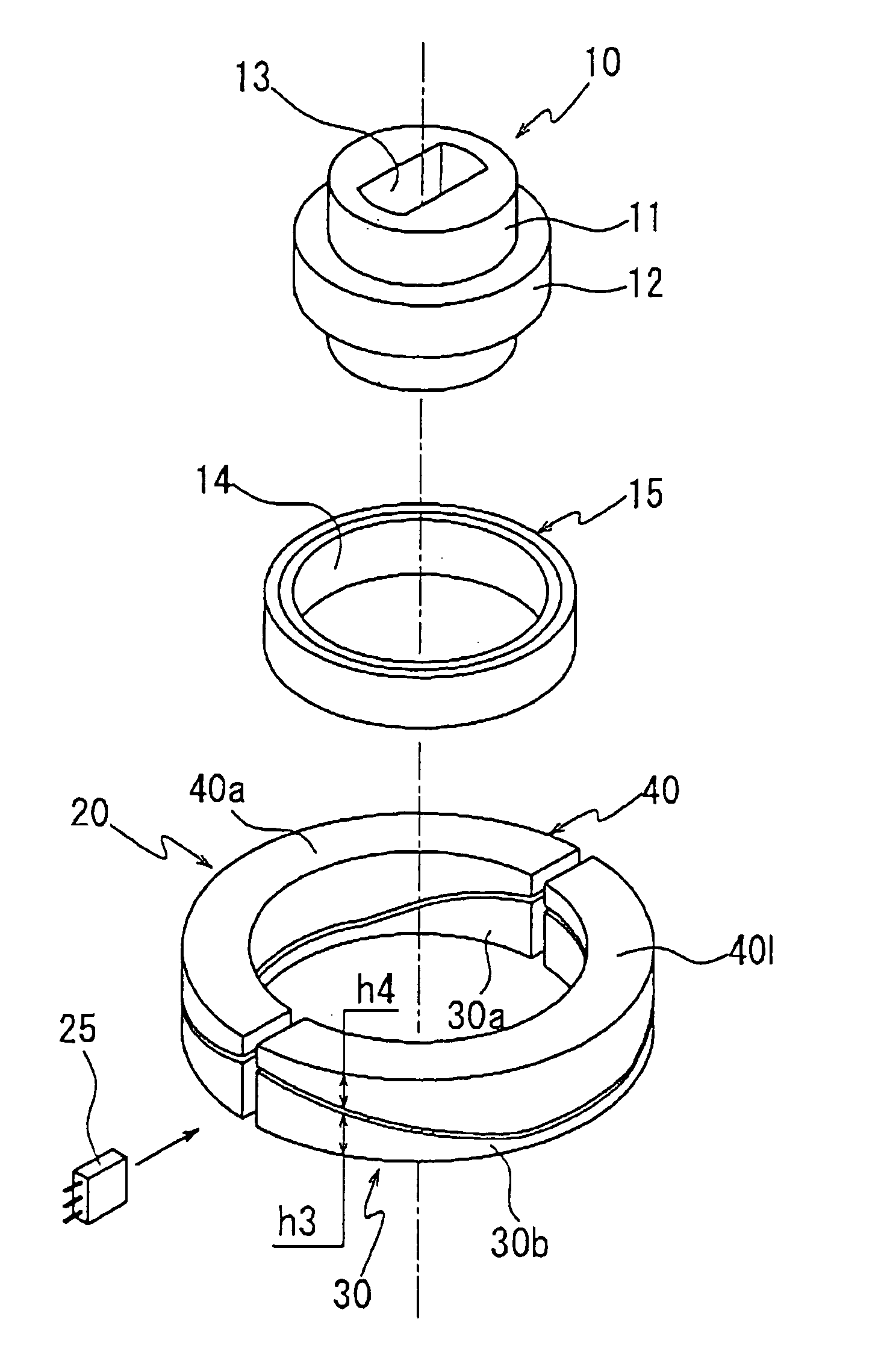
[0047]As one example, the ring-shaped permanent magnet 15 uses an isotropic, neodymium bond magnet (molding neodymium, iron, and boron powder with PPS plastic) and has an inner diameter of 21 mm, an outer diameter of 23 mm, a height of 5 mm, a surface magnetic flux density of 75 mT and the support yoke 14 has an inner diameter of 19 mm, an outer diameter of 21 mm, and a height of 5 mm.

[0048]In the first outside yoke 30, each of the two semi circle portions 30a and 30b has a width (W) of 4 mm, the maximum portion of the height h3 of 6 mm at both ends of the circular arc, the minimum portion in a concave shape of 1 mm at a center of the circular arc, a width (G) of 1.6 mm of the gap produced by cutting off the both ends by 0.8 mm each and in the second outside yoke 40, each of the two semi circle portions 40a and 40b has a width (W) of 4 mm, the maximum portion of the height h3 of 6 mm at both ends of the circular arc, the minimum portion of 1 mm in a convex shape at a center of the c...


PUM


Abstract

A stationary yoke surrounds an outer peripheral surface of a ring-shaped permanent magnet in a certain distance. The ring-shaped permanent magnet is fixed to a rotor and has two poles of N, S poles in a diameter direction. The stationary yoke includes a first outside yoke and a second outside yoke overlapped in an axial direction and a hole element is disposed in a gap of the first outside yoke. An axial height of the first outside yoke changes along the circumferential direction and a height of the second outside yoke has a complementary relation with the height of the first outside yoke, and the first outside yoke and the second outside yoke are overlapped in a certain clearance. A ratio of an amount of the magnetic flux passing through the gap to an amount of the magnetic flux not passing through the gap changes with rotation of the ring-shaped permanent magnet and further, the change of the height causes a change in the magnetic flux amount flowing in the first outside yoke, thereby improving linearity of an output of a hole element.

Description

BACKGROUND OF THE INVENTION[0001]1. Field of the Invention[0002]The present invention relates to a non-contact rotation angle detecting sensor using a magnetic responsive element.[0003]2. The Related Art of the Invention[0004]As a rotation angle sensor, for example, suitable for detecting a depressing angle of an accelerator pedal or detecting a rotation angle of a shaft rotating in accordance with an operation of shift lever for a vehicle, which is portable and has no possibility of contact defect due to a foreign matter, there is a non-contact rotation angle sensor using a magnetic responsive element.[0005]Japanese Unexamined Publication No. 5-505883 has disclosed, for example, a conventional example of such a non-contact rotation angle sensor.[0006]In this conventional example, as shown in FIG. 7A, a ring-shape permanent magnet 100 which is divided in a semi circle is fixed to a rotor (not shown) to form two poles, N and S in a diameter direction, and on the other hand, an outer ...

Claims


Application Information

Patent Timeline
Patent Type & Authority Patents(United States)
IPC IPC(8): G01B7/30
CPCG01D5/145G01B7/30G01B7/14
Inventor SATO, SHUNICHI
Owner SATO SHUNICHI
Features
  • R&D
  • Intellectual Property
  • Life Sciences
  • Materials
  • Tech Scout
  • Unparalleled Data Quality
  • Higher Quality Content
  • 60% Fewer Hallucinations
Learn More